Descriptions
28
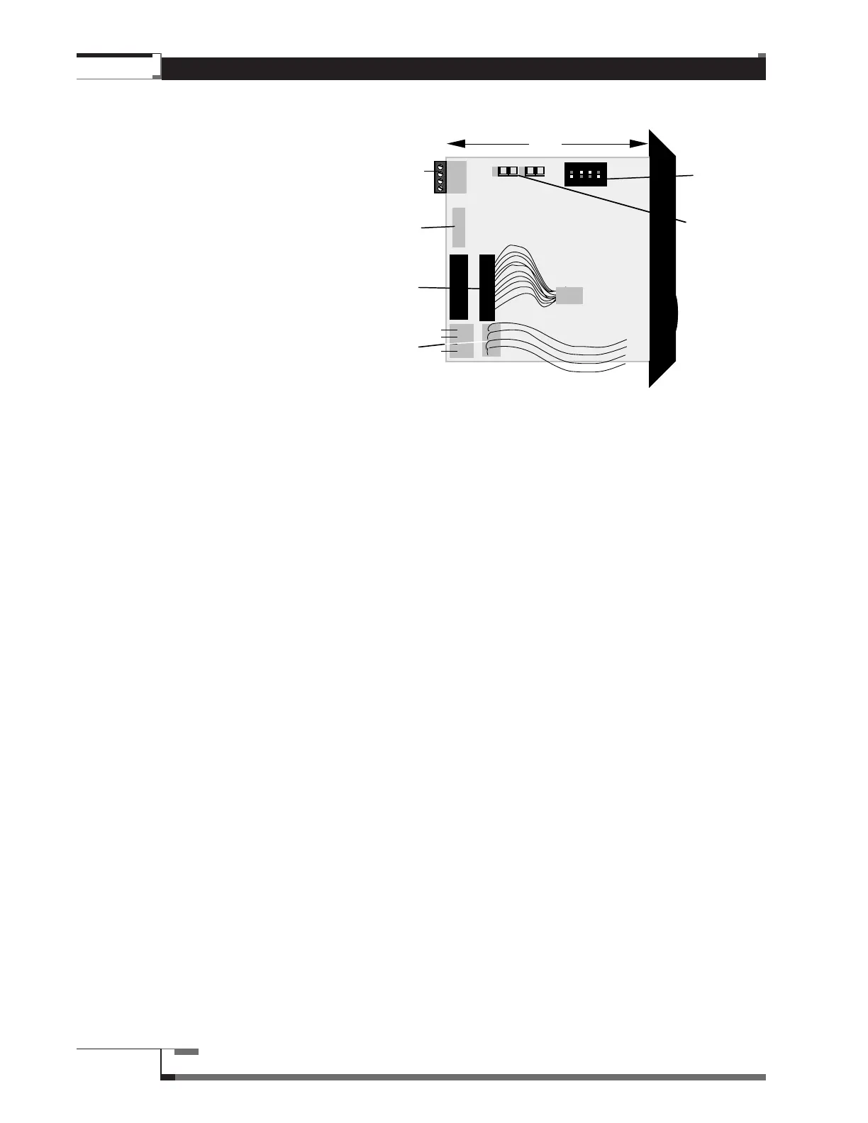
MVP Watt Meter, Side View
A. Audio Signal Terminal – Allows
the Watt Meter to be connected
to the Amplifier-Speaker bus.
B. Switching Module Connector –
like Switching Module
Connectors on Dual Chain
Modules (see page 25) –
connects the single Chain on the
Watt Meter to the first Switching
Module in its associated Chain.
C. Parallel Data Connectors –
connect the single Chain on the
Watt Meter to other Chain
Modules and to the Control
Module.
D. Parallel Power Connectors – connect power to and from the next Chain or Feature
Module.
E. DIP Switch – like DIP Switches on Dual Chain Modules for CH1 (see page 25).
F. Speaker Impedance Level Jumpers – allows choice of Speaker impedance level
(4 ohm or 8 ohm) for Watt Meter. These are set during installation, but can be changed at
any time. The settings of these jumpers will affect the response of the Watt Meter
measurements. See page 70 for Installation instructions. If 1 ohm or 2 ohm impedance
levels are needed, call MTi.
Figure 11 – MVP Watt Meter,
Side View
CH1
ON
4 L 8 4 R 8
L+L-R+R-
E
B
C
A
D
F
3 "
1
/
2