2-5
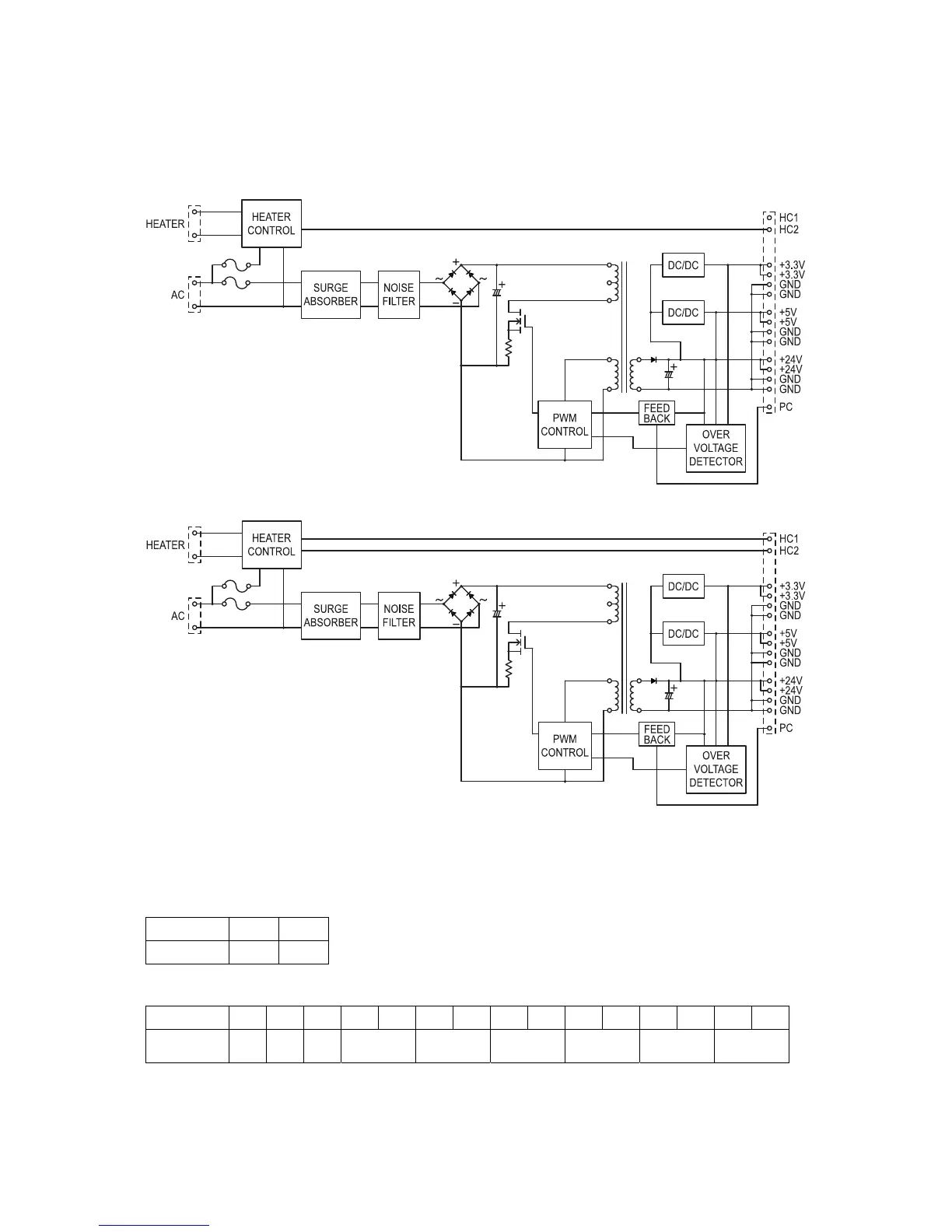
2.4 Power Supply Unit (PSU)
The power supply unit receives the input line voltage and currents it to output voltages of +3.3DVC, +5
VDC and +24 VDC.
The heater circuit controls output voltage to the fuser heater according to instructions received from
the heater control circuit.
If an over-current is sensed in the secondary circuit, power is interrupted.
Power supply unit block diagram for US
Power supply unit block diagram for Europe
The power supply unit has two output connectors.
The following table shows the connector outputs:
CN101 -- to the Fuser Heater
Pin No. 1 2
Output L N
CN2 -- to the Main Control PCB.
Pin No. 1 2 3 4 5 6 7 8 9 10 11 12 13 14 15
Output
voltage
PC HC1 HC2 +5V SG +3.3V SG +24V PG
 Loading...