2-16
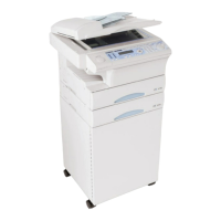
Fusing Temperature Control Circuit
The Thermistor detects the surface temperature of the Heater Roller and inputs that analog voltage
into the Main Control PCB. Corresponding to this data, the Heater Lamp ON/OFF signal is output to
the Heater ON/OFF switch of the power supply unit, causing the Heater Lamp to turn ON or OFF to
control the fusing temperature.
When the Heater Lamp is not turned OFF even if the Thermistor detects a high temperature
malfunction, the thermostat shuts down the power to the heater lamp. When the thermostat is
malfunction, the thermal cut-off shuts down the power to the heater lamp.
L
N
Main Control PCB
Fusing temperture
control circuit
Power supply unit
AC Inlet
Fusing unit
Thermistor
Heater Lamp
Thermostat
Thermal cut-off
Heater
on/off
switch
Main switch
Fusing temperature
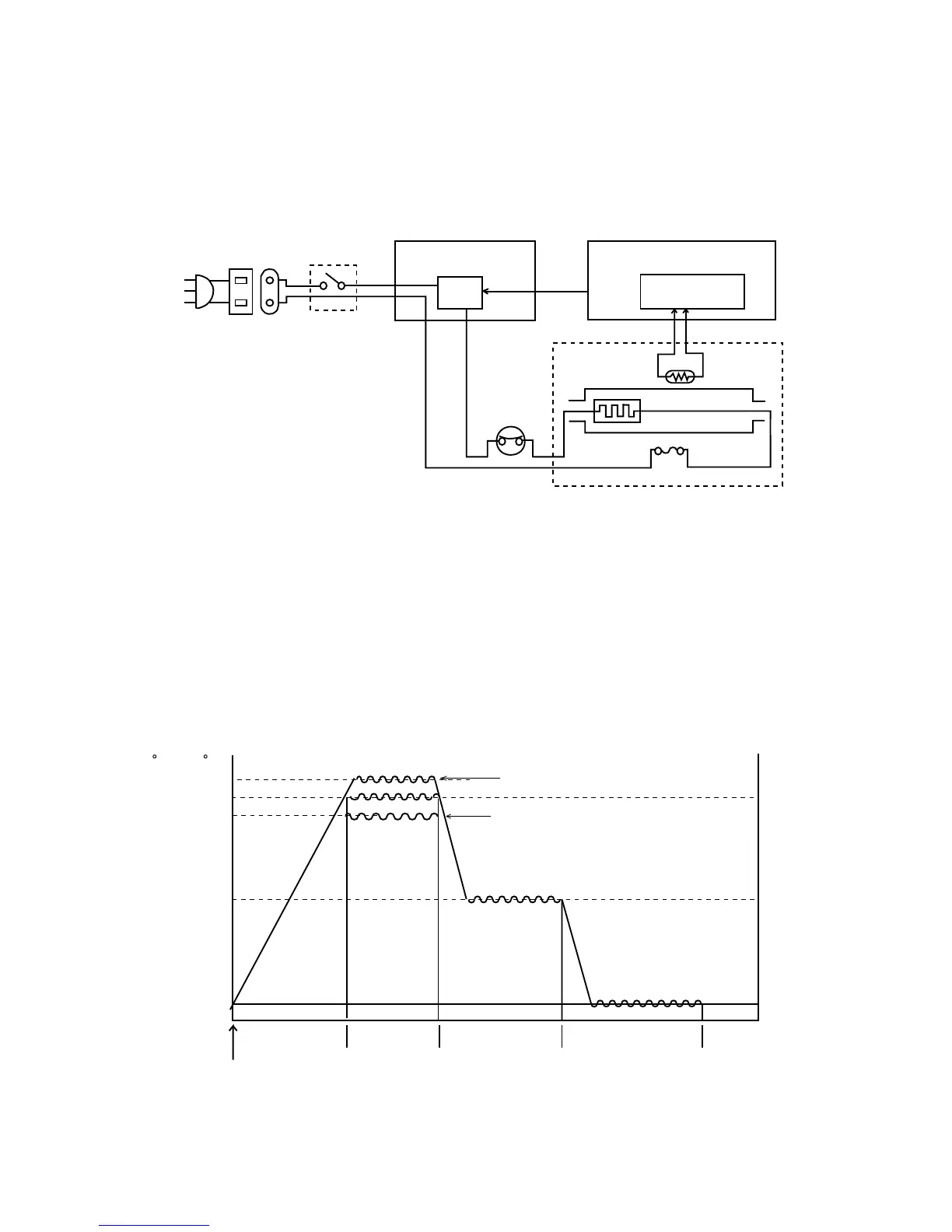
1) Warming Up After the initialization of the printer, warming up of the printer starts and the
Heater Lamp turns ON until the temperature of the Heater Roller reaches
approx. 200 °C.
2) Printing When the printer obtains the printing command from its controller, the Heater
Roller is maintained at 200 °C.
After printing, the printer turns to standby mode. The fuser kept at low
temperature.
3) Standby mode The Heater Roller maintained at approx. 130°C.
4) Energy save mode In this mode, saving the power.
Temperature
( F) ( C)
Power ON
Warming
up
Time
Printing
Standby mode
200
205
130
392
401
248
Energy save mode
Post card printing only
OHP
195393

 Loading...