Suspension and wheels
F
- 24 -
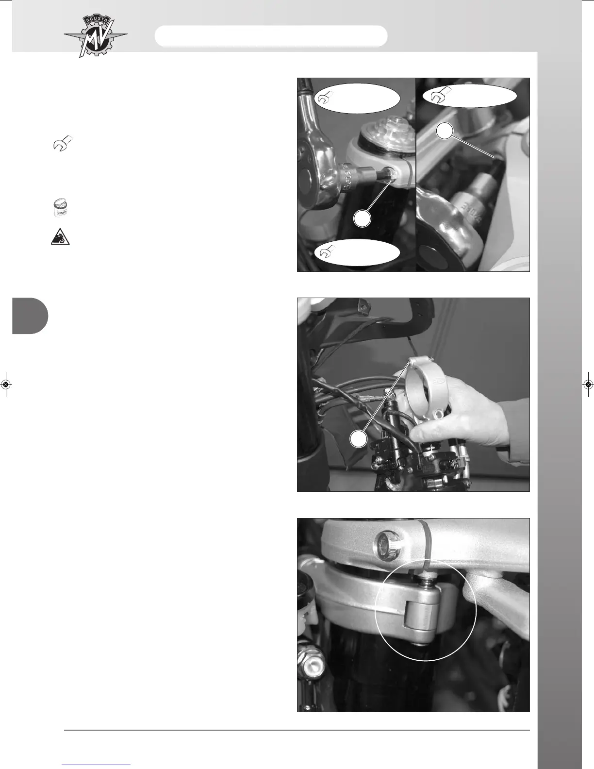
Assemble the clip-on handlebar slotting the clamp pin
into position on the steering head (see figure).
Clip-on handlebars assembly
Position the electrical wiring as shown in the figure.
Ensure that the Seeger retaining ring (1) of the clamp
pin is in good condition and in position.
1
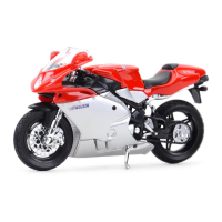
Ensure that the steering head is sitting perfectly in its
seat. Tighten the two screws (2) of the steering
head/stems to the prescribed torque pressure and suc-
cessively tighten the central screw (3).
Torque pressure - Steering head screws (2):
- F4 S / FT / R / F4 MY13: 16 ÷ 18 N·m
- F4 RR: 18 ÷ 22 N·m
Torque pressure - Central screw (3):
22 ÷ 24 N·m
Grease only the first threads.
This check is necessary for the correct
positioning of the stems even if the steering
head has not been removed. This check
guarantees the standard set-up of the
motorcycle.
22÷24 N•m
2
3
F4 S - FT - R
- F4 MY13:
16÷18 N•m
F4 RR:
18÷22 N•m