B-1
Annex B: Determining the matrix
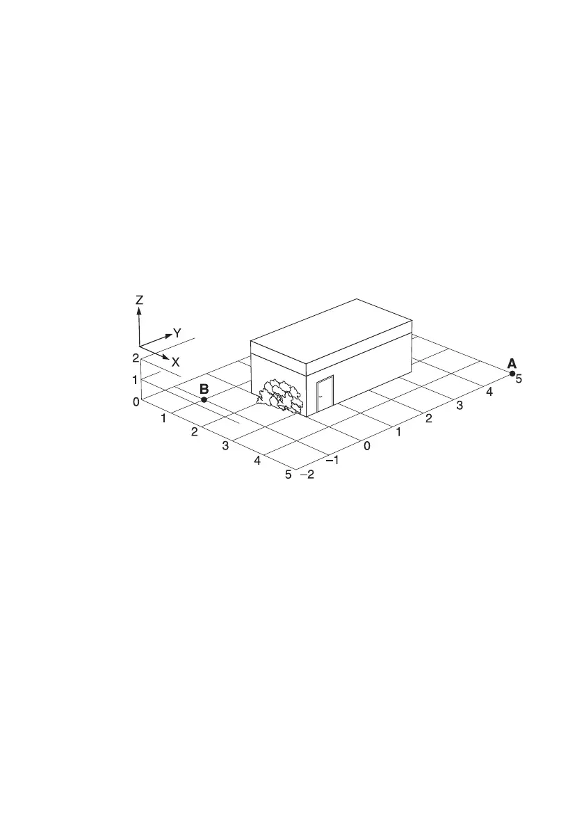
Defining the spatial area and spatial points
The actual space within which the measurement is to be made (e.g. an
office or the area around a transformer station) is represented by a
coordinate space.
Every point in this space can be described exactly by means of a set of
coordinates. The user assigns a coordinate axis (x, y, z) to each of the three
spatial axes (e.g. length, width, height). The spatial limits are described by
the coordinates of the two limiting points, designated “A” and “B” in the
diagram.
Figure B-1 Overlaying an imaginary coordinate space around the object under
investigation
Coordinates that lie within these coordinate limits (spatial limits) can be
selected as required. Visualization can be improved by using positive and
negative values. The limits can be changed at any time during the
measurement to allow additional areas of interest to be included in the set
of measurements.
One or two coordinates can be set to any fixed value for measurement
points located on a surface or line.