Get Started
21
XS708T, XS712Tv2, and XS716T Smart Managed Pro Switch User Manual
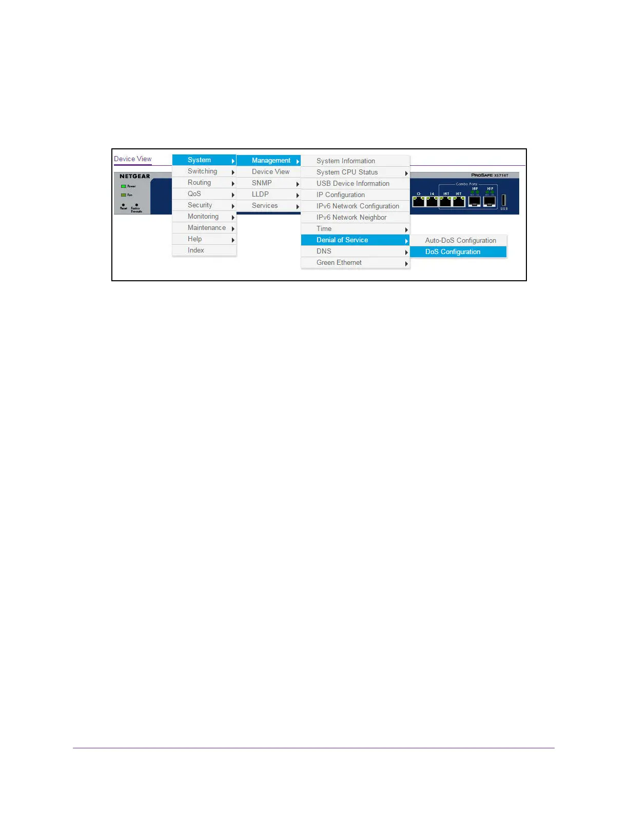
You can select a menu option to access the page that contains the configuration or
monitoring options.
If you right-click the graphic, but do not right-click a specific port, the main menu displays.
This menu contains the same options as the navigation tabs at the top of the page.
Right-click the specific port that you want to view or configure to see a menu that displays
statistics and configuration options. Select the menu option to access the page that
contains the configuration or monitoring options.
The system LEDs are located on the left side of the front panel.
Power LED
The Power LED is a bicolor LED that serves as an indicator of power and diagnostic status:
• Solid green. The power is supplied to the switch and operating normally.
• Solid yellow. The system is in the boot-up stage.
• Off. No power is supplied to the switch.
Fan LED
The Fan LED indicates the following status:
• Solid yellow. The fan is faulty.
• Off. The fan is operating normally.
Interface Naming Conventions
The switch supports physical and logical interfaces. Interfaces are identified by their type and
the interface number. The physical ports are Gigabit interfaces and are numbered on the
front panel. You configure the logical interfaces by using the software.

 Loading...