13-28 Cabinet and equipment wiring and cabling
AccessNode 323-3001-210 Issue 1.0
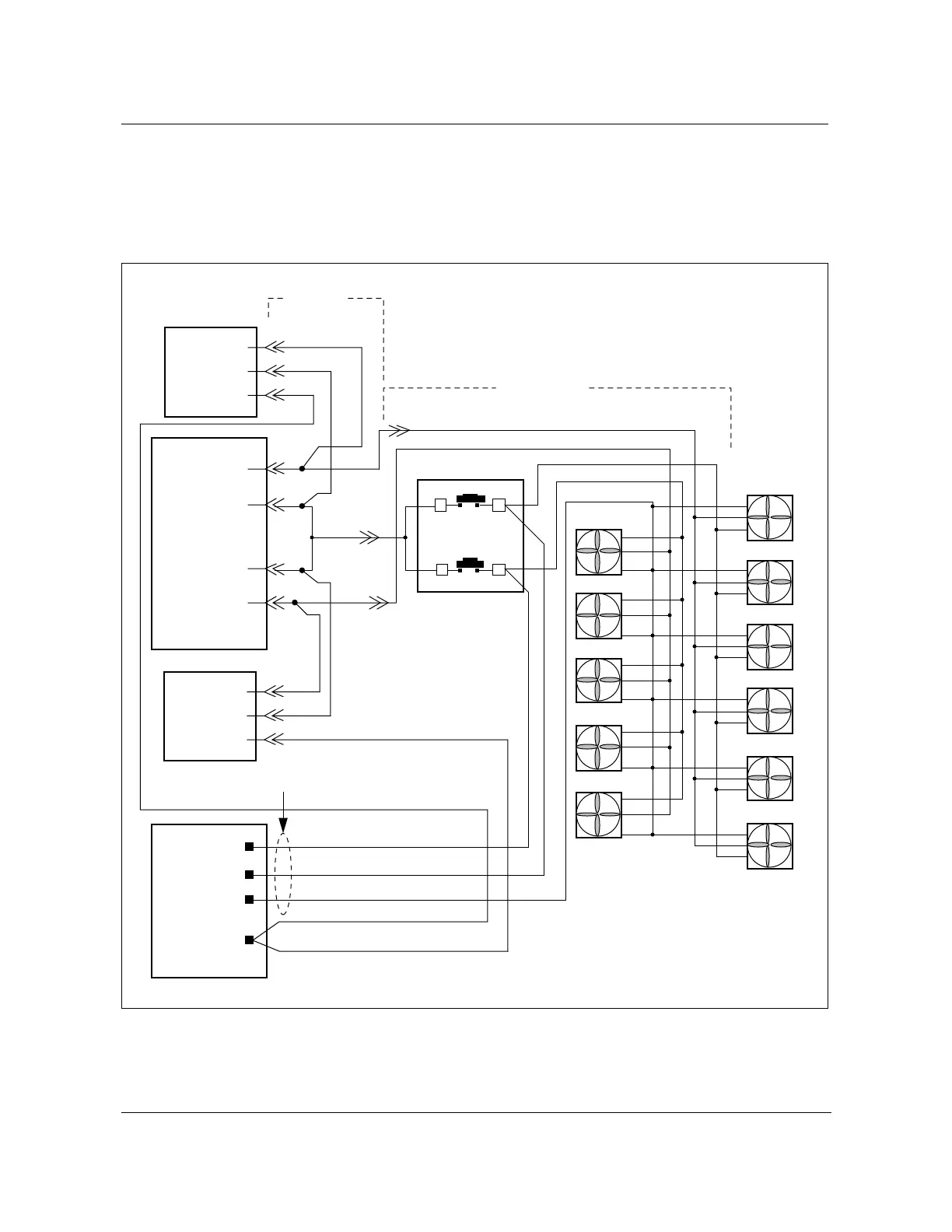
Fan power wiring
Circuit breakers CU A and CU B feed dc power to the fan units. Figure 13-18
details the fan powering diagram for dc power from the BIP.
Figure 13-18
BIP Fan powering wiring diagram
FW-15249
CU A
CU B
-48V
BR
-48V
BR
+
-
+
-
+
-
+
-
+
-
+
-
+
-
+
-
+
-
+
-
+
-
BK
BL
BK
Battery
breaker
panel
Fan
9
(IN)
BIP
P2.1
P2.2
P3.2
P3.1
P1.1
P1.2
BK
R
W
WBK
7
11
12
Alm
Alm
Alm
Alm
Alm
Alm
Alm
Alm
Alm
Alm
Alm
NT1W87
NT7A6980/82
W
12
34
FW-15249
P4.1
P4.2
P4.3
P5.1
P5.2
P5.3
P1.3
R
RBK
SL
SL
Alarm circuit BR CU A (BK)
Alarm circuit BR CU B (BK)
Fan group 2
Fan group 1
Fan shelf fail alarm (SL)
Fan shelf fail alarm (SL)
Roof fan fail alarm (BL)
Fan
shelf 1
Fan
shelf 2
Part of NT7A6980