13-38 Cabinet and equipment wiring and cabling
AccessNode 323-3001-210 Issue 1.0
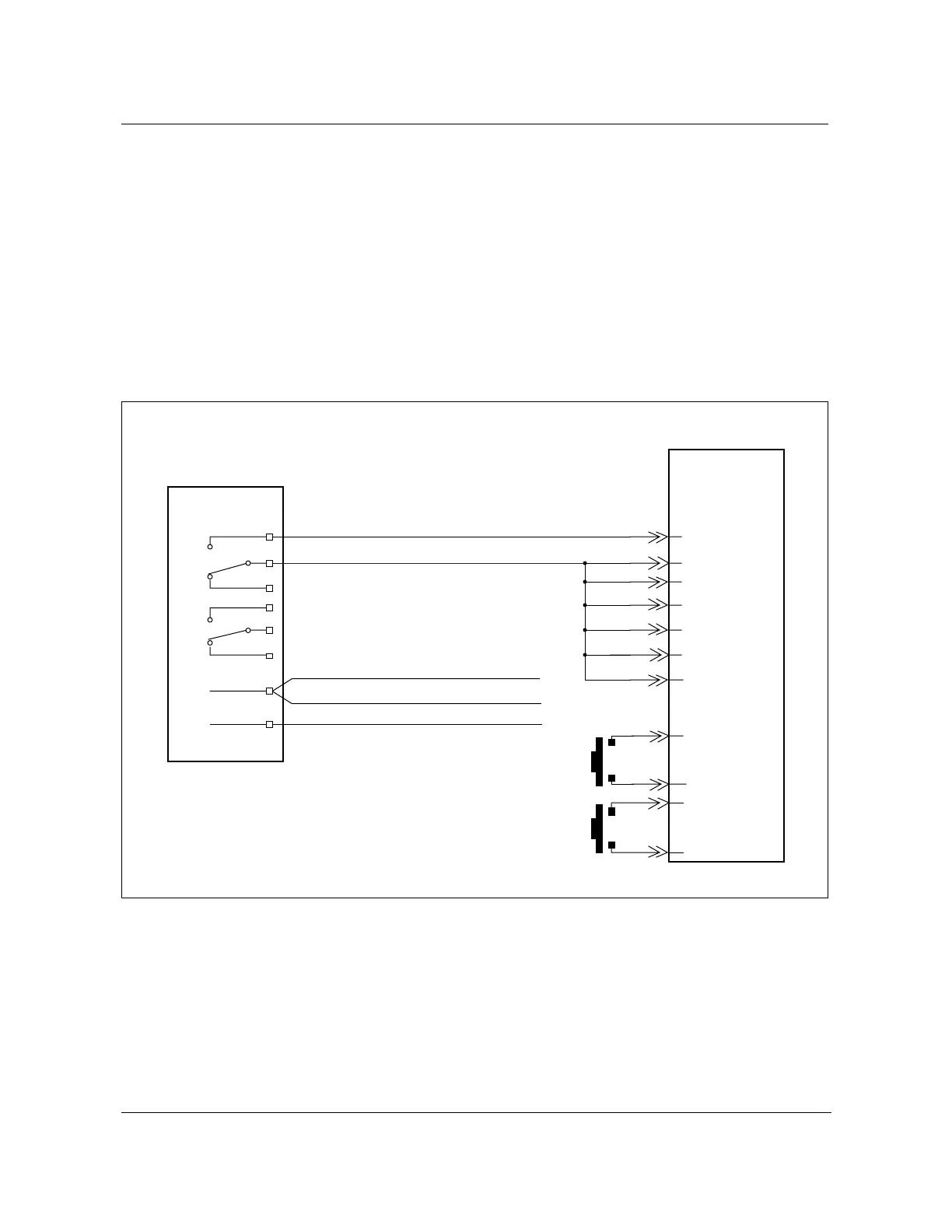
Fan and Temperature alarm circuit
Fan and high temperature alarm wiring in the S800A cabinet is connected from
the fan assemblies (see Figure 13-18 on page 13-28) to the BBP and then
to the SIL.
The low temperature alarm sensor is wired to the BIP wire-wrap block
pins 7 and 8.
Figure 13-26 shows the fan and temperature alarm wiring diagram to the ABM
shelf SIL (J05) from the BBP.
Figure 13-26
SIL J05 FAN and TEMP alarm circuit wiring diagram
FW-15250
BBP
1
2
3
4
5
6
9ALM In 2
Thermostat
close above
+ 60˚C
J05
SIL
NT4K50AA
Thermostat
close bellow
+ 60˚C
9
1
2
3
4
5
6
25
23
10
24
NT1W82FA
Fan
LGND
YHITMPA
LGND
LGND
YFANSTA1
YFANSTA2
YFANSTA3
YFANSTA4
YFANSTA5
YFANSTA6
YHITMPB
FW-15250
7ALM In 1
SL - from fan shelf 1 (Part of NT1W87AB)
SL - from fan shelf 2 (Part of NT1W87AB)
BL - from roof fans (Part of cable NT7A6980)
From fan alarm
outputs