EasyManua.ls Logo

Numatics G3 Series - Page 119

Numatics G3 Series
164 pages
Print Icon
To Next Page IconTo Next Page
To Previous Page IconTo Previous Page
Loading...
G3 Series EtherNet/IP
TM
DLR Technical Manual
11-119
TDG3EDM1-6EN 3/18
Subject to change without notice
www.asco.com/g3
Error/Event Messages
The following are error messages that are displayed when specific faults/events occur during operation:
Connector Pin Out
5
FEMALE
PIN 1 = Shield
PIN 2 = V+
PIN 3 = V-
PIN 4 = CAN_H
PIN 5 = CAN_L
Displayed when a Sub-Bus module that had been
previously installed becomes absent from the
configuration
Displayed when a Sub-Bus power short circuit
condition is detected
MISSING MODULE
NUMBER XX
SUB-BUS
SHORT CIRCUIT
Length of molded or field wired Sub-Bus Branch cables should not exceed the maximum
length of 30 meters per Sub-Bus Branch communication link.
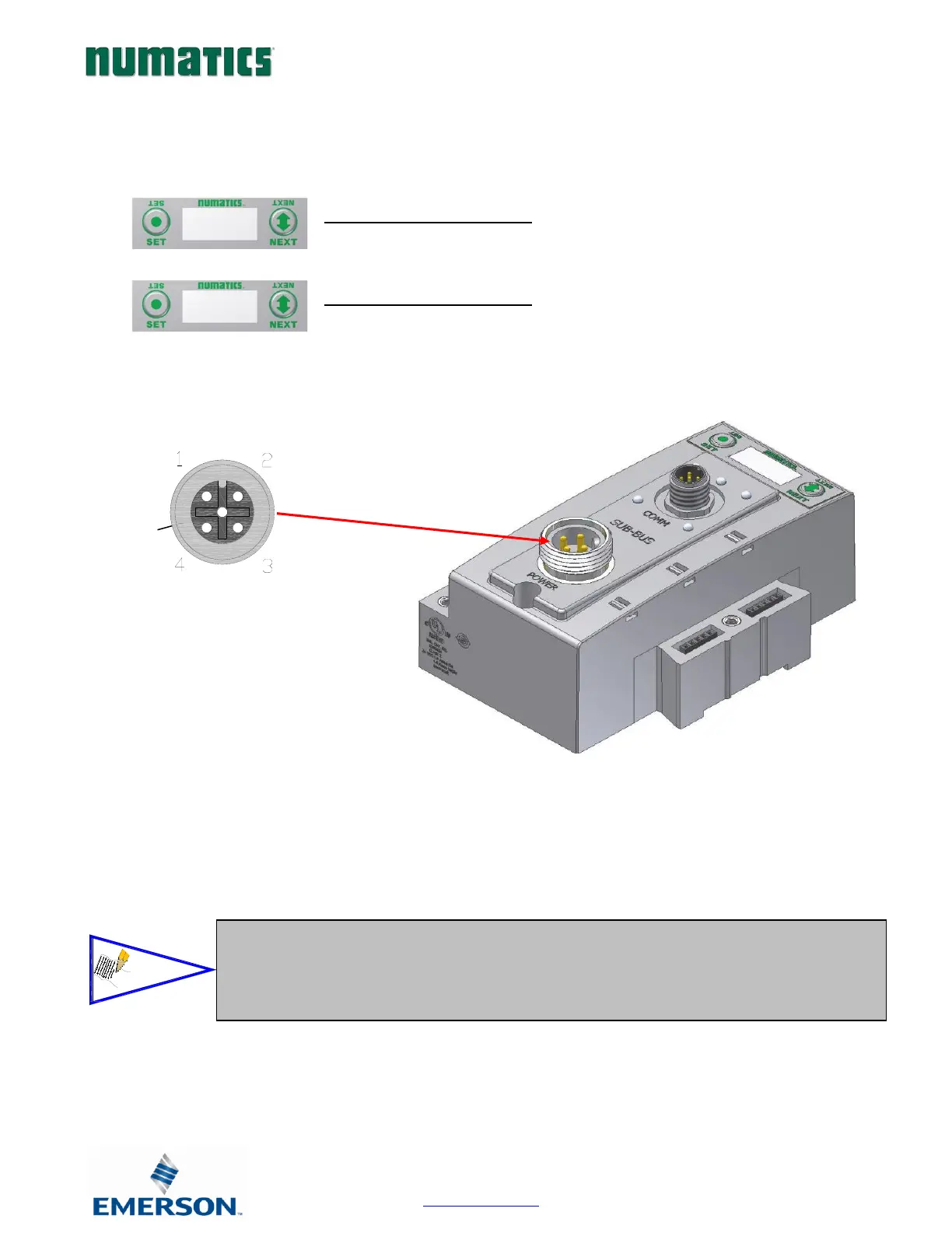
The molded cable assemblies and bulk cable are the only approved cables for the G3 Sub-Bus
and Branch Link. Please refer to the G3 Electronics catalog (LT-G3Catalog), for Sub-Bus cable
and connectors options. See Technical Document TDG3SBWD1-0EN for proper installation
and wiring of field wire-able connectors.
NOTE!

Table of Contents

Related product manuals