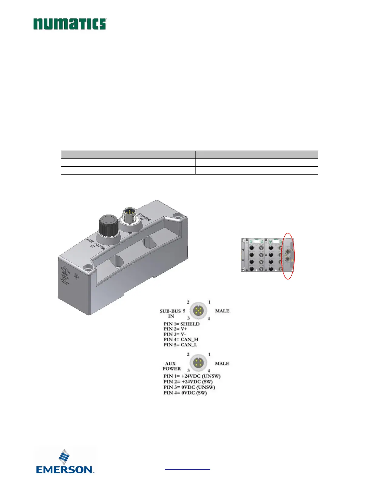
SUB-BUS IN Modules
• Used to distribute I/O assemblies that do not have valves
o Must be installed to the right of the I/O modules.
• SUB-BUS IN - 5 pin M12 male communication connector.
• Must be connected to the Sub-Bus Out connector of the previous assembly
• Carries 24 VDC power for electronics of module
• AUX. POWER IN - 4 pin M12 male connector.
• Aux power is required for Output modules. This connection also allows Output power to be interrupted to
all Output modules connected to this module.
• Aux. Power is optional for Inputs. Power from the SUN-BUS IN connection is used to power
sensors but can be augmented, if necessary, by adding additional power to this connector.