USB and PCI Express
NVIDIA Jetson Nano DG-09502-001_v2.1 | 26
6.3 Gigabit Ethernet
Jetson Nano integrates a Realtek RTL8119I-CG Gigabit Ethernet controller. The magnetics
and RJ45 connector would be implemented on the carrier board. Contact Realtek for carrier
board placement and routing guidelines.
Table 6-11. Jetson Nano Gigabit Ethernet Pin Description
Pin # Module Pin Name Tegra X1 Signal Usage/Description
Usage on NVIDIA DevKit
Carrier Board
Direction Pin Type
Code
Power-on
Reset
194 GBE_LED_ACT − Ethernet Activity LED (Yellow)
LAN
Output − − −
188 GBE_LED_LINK − Ethernet Link LED (Green) Output − − −
184 GBE_MDI0_N
−
GbE Transformer Data 0
Bidir MDI
− −
186 GBE_MDI0_P − − −
190 GBE_MDI1_N −
GbE Transformer Data 1
− −
192 GBE_MDI1_P − − −
196 GBE_MDI2_N
−
GbE Transformer Data 2
− −
198 GBE_MDI2_P − − −
202 GBE_MDI3_N −
GbE Transformer Data 3
− −
204 GBE_MDI3_P − − −
Notes:
1. In the Type/Dir column, Output is from Jetson Nano. Input is to Jetson Nano. Bidir is for Bidirectional signals.
2. The MPIO Pad Codes are described in the
Tegra X1 SoC Technical Reference Manual
“Multi-Purpose I/O Pins and Pin Multiplexing
(PinMux)” section for details.
3. The Power-on Reset State column indicates the pin state when reset is active and when it is deactivated before any changes are made by
software. “z” is tristate, pu/pd indicates internal weak pull-up/down resistor is enabled, 1/0 indicates actively driven high/low.
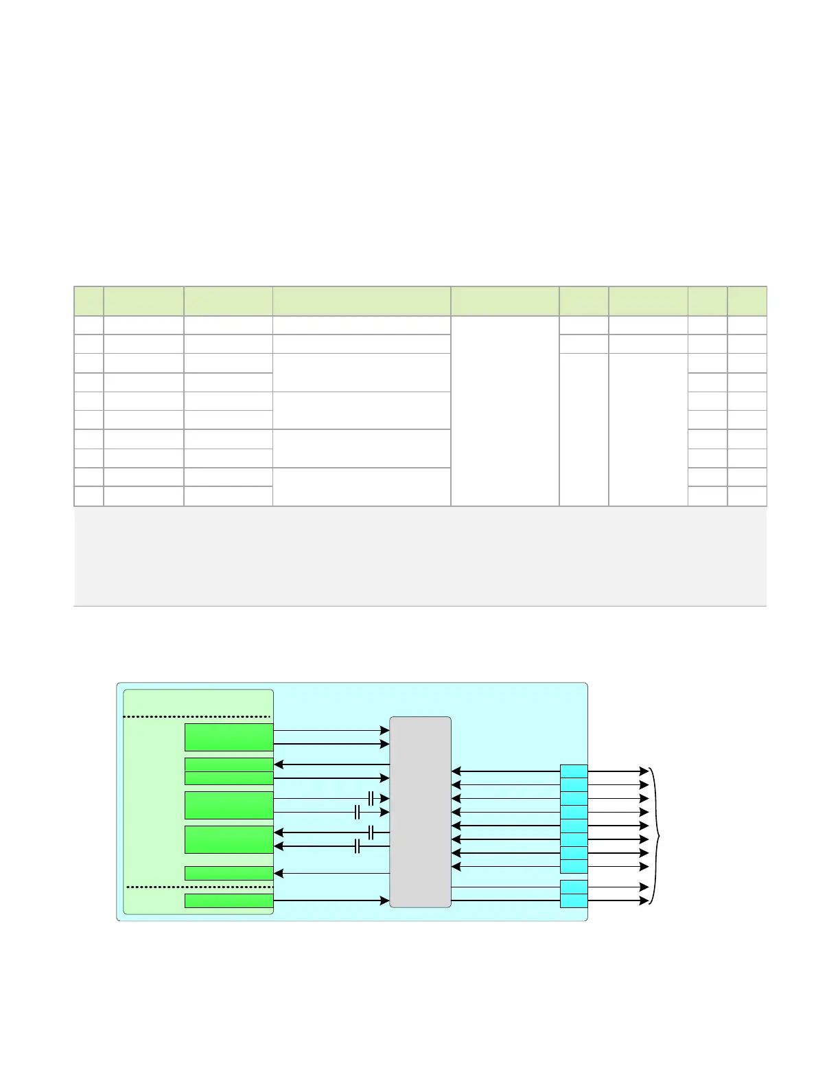
Figure 6-9. Jetson Nano Ethernet Connections
Jetson
Tegra
USB 3.0
& P EX
PEX_TX0_N
PEX_TX0_P
Ethernet
PHY
PEX_RX0_N
PEX_RX0_P
GBE_MDI0_P
GBE_MDI0_N
GBE_MDI1_P
GBE_MDI1_N
GBE_MDI2_P
GBE_MDI2_N
GBE_MDI3_P
GBE_MDI3_N
GBE_LED_ACT
GBE_LE D_LINK
To Magnetics/
RJ45 Connector
186
184
192
190
198
196
204
202
194
188
PEX_WAKE
SYS
ALS_PROX_INT
I SOL ATE *
LANWAKEB
PEX_CLK2_N
PEX_CLK2_P
PEX_L1_CLKREQ
PEX_L1_RST

 Loading...


