45530603TH Rev.2
4-89
Oki Data CONFIDENTIAL
4. TROUBLESHOOTING PROCEDURE
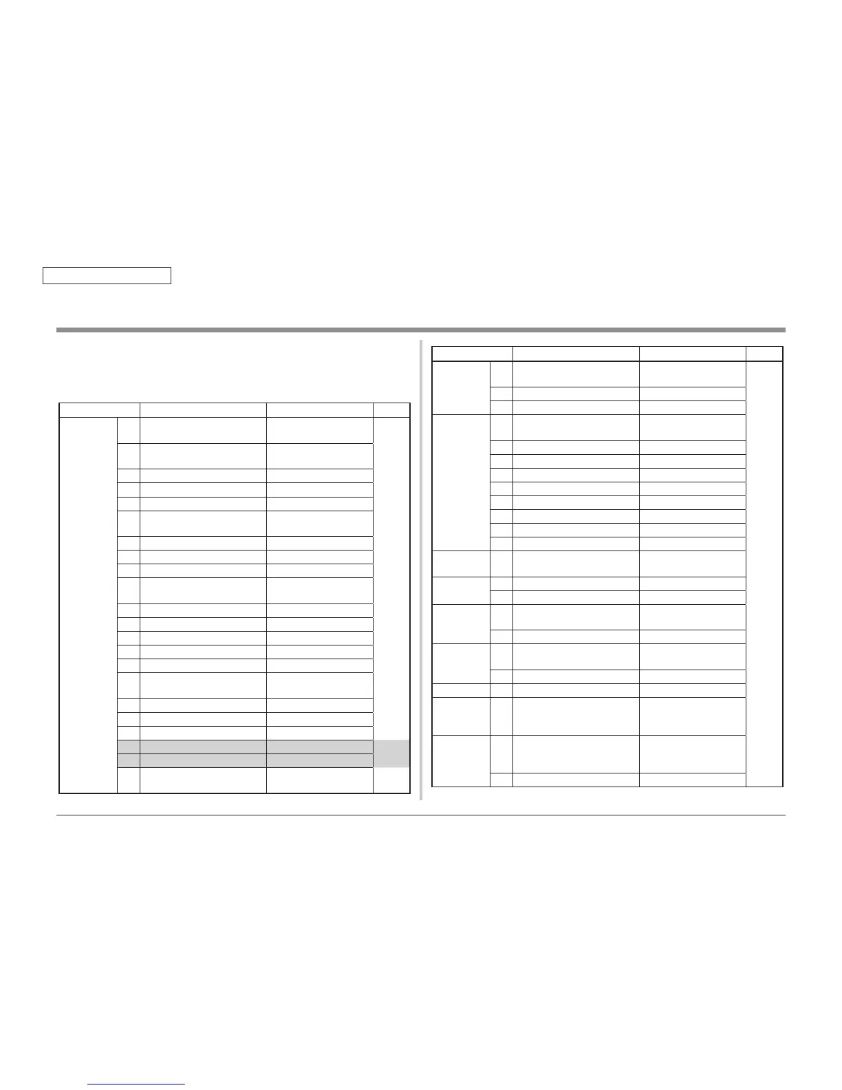
If any of the following errors occurs, check the corresponding fuse on the PU/CU control PCB
or high voltage power supply board.
(Refer to Table 4-6.)
Ta bl e 4 -6 F us e er r or
Fuse Name Error Description Insert Point Resistance
Printer
controller PCB
F1 Not recognition Option Option Tray : 5V
1Ω
or
less
F2 Not displayed operator panel, Not
start of initialization
CPU arround : 5V
F3 DUPLEXFAN Error DUPLEX :24V
F4 Not recognition of DUPLEX DUPLEX : 5V
F5 Feed JAM Option Tray : 24V
F6 Shout down(LED of Power Supply
switch blink)
engine : 5V
F7 TR2 position error or TR2 FAN error Rail unit : 24V
F8 TR2 position error or Rail unit : 5V
F9 BELT motor lock erroe BELT motor
F10 Front cover open High voltage power supply :
24V,Low voltage FAN
F11 FEEDJAM FEED motor, Lift up motor
F12 SC128 FAN, Clutch
F13 Shout down Supply 5V when sleep mode
F14 FUSER motor lock error FUSER, BELT motor
F15 SC121 High voltage interface error High voltage power supply : 5V
F16 FEEDJAM IN sensor, Color registration
sensor
F17 Not recognition HDD SATA power
F18 SC188-02 FUSER thermistor/ Driver relay
F19 SC231-01 TAGR/W PCB
F20
-
Not install
F21
-
Not install
F22 Not displayed operator panel, Not
start of initialization
OPE : 3.3V
4.6 Fuse check
Fuse Name Error Description Insert Point Resistance
Printer
controller PCB
F23 Not displayed operator panel, Not
start of initialization
OPE,PT Paper
width,Environmental sensor
1Ω
or
less
F24 EXIT cover open Driver relay PCB
F25 SC134 LED head : 3.3V
Driver relay
PCB
F1 Up/Down error Toner low, ID Up/Down
F2 ID motor lock error ID motor
F31 SC147 Toner supply Motor C,K
F32 SC147 Toner supply Motor Y,M
F33 Spot color duct open Toner supply Motor Spot
F4 Spectrum Discharging light
F5 SC128 IDFAN
F6 SC128 Fuser FAN
F7 JOBOFF Home position error EXIT sensor, Joboff sensor
Control Panel
PCB
F1 Not displayed operator panel LCD power
Dulex Unit PCB F501 SC128 DUPLEXFAN error 24V, Actuater, FAN
F502 Not recognition DUPLEX 5V, DUPLEX mycom
Option Tray
PCB
F501 Option Tray hopping JAM 24V, Actuater
F502 Not recognition Option Tray 5V, Option mycom
Head relay PCB F501 Spot color, Yellow, Magenta not
printing
Spot color, Yellow, Magenta
LED head : 5V
F502 Cyan, Black not printing Cyan, Black LED head : 5V
Spot color PCB F1 SC134 Spot color LED head : 3.3V
High voltage
power supply
PCB
F501 Front cover open Front cover SW and High
voltage trance power supply
Low voltage
power supply
PCB
F001 Shout down Main power
F002 Shout down Main power

 Loading...