DMTA-20073-01EN, Rev. C, November 2015
Maintenance
103
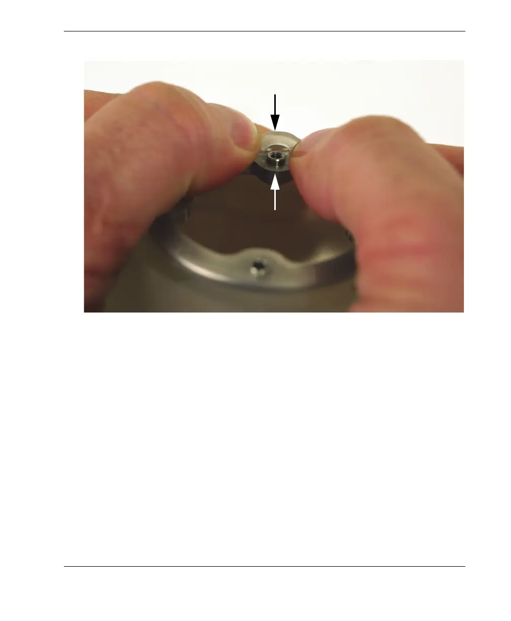
Figure 6-30 Installing a ring in its retaining groove in the tire
e) Insert the other stainless steel ring by repeating steps 6.a to 6.d.
7. Install the flange that contains the liquid-control valves. Do the following:
a) Align the captive screws on the stainless steel ring to the holes on the flange
(see Figure 6-31 on page 104).
Carefully aligning and inserting the posts in the holes of the tire lip