DMTA-20073-01EN, Rev. C, November 2015
Chapter 6
130
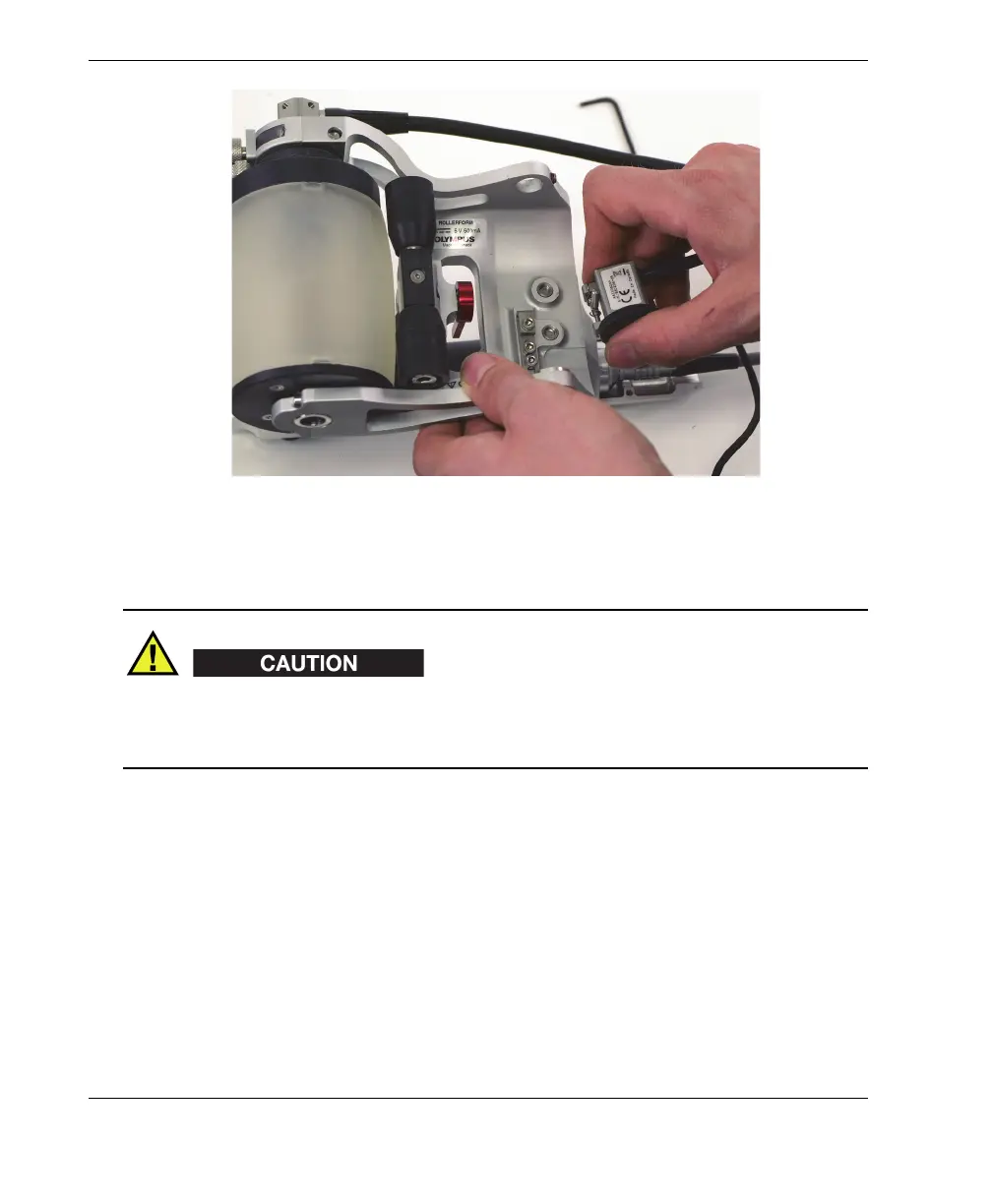
Figure 6-56 Removing the Mini-Wheel encoder
To prevent bending the primary encoder holder bracket, do not overtighten the
encoder retaining screw. A bent bracket renders it difficult to install the encoder on
the primary holder.
6. With the encoder removed, tighten the encoder retaining screw into the
RollerFORM frame.
7. Install the rear roller. Do the following:
a) Position the rear roller in place inside the RollerFORM frame.
b) Insert the tip of the rear roller’s axle into the entry/exit hole equipped with a
retaining screw.
c) Then, thread the axle through the rear roller until it enters the axle seat on the
other side of the RollerFORM frame.
Make sure that the flat bevel of the axle end is facing the rear roller retaining
screw (see Figure 6-57 on page 131).