EasyManuals Logo

Omron CP1E Series User Manual

Omron CP1E Series
260 pages
To Next Page IconTo Next Page
To Previous Page IconTo Previous Page
Page #72 background imageLoading...
Page #72 background image
3 Part Names and Functions
3-8
CP1E CPU Unit Hardware User’s Manual(W479)
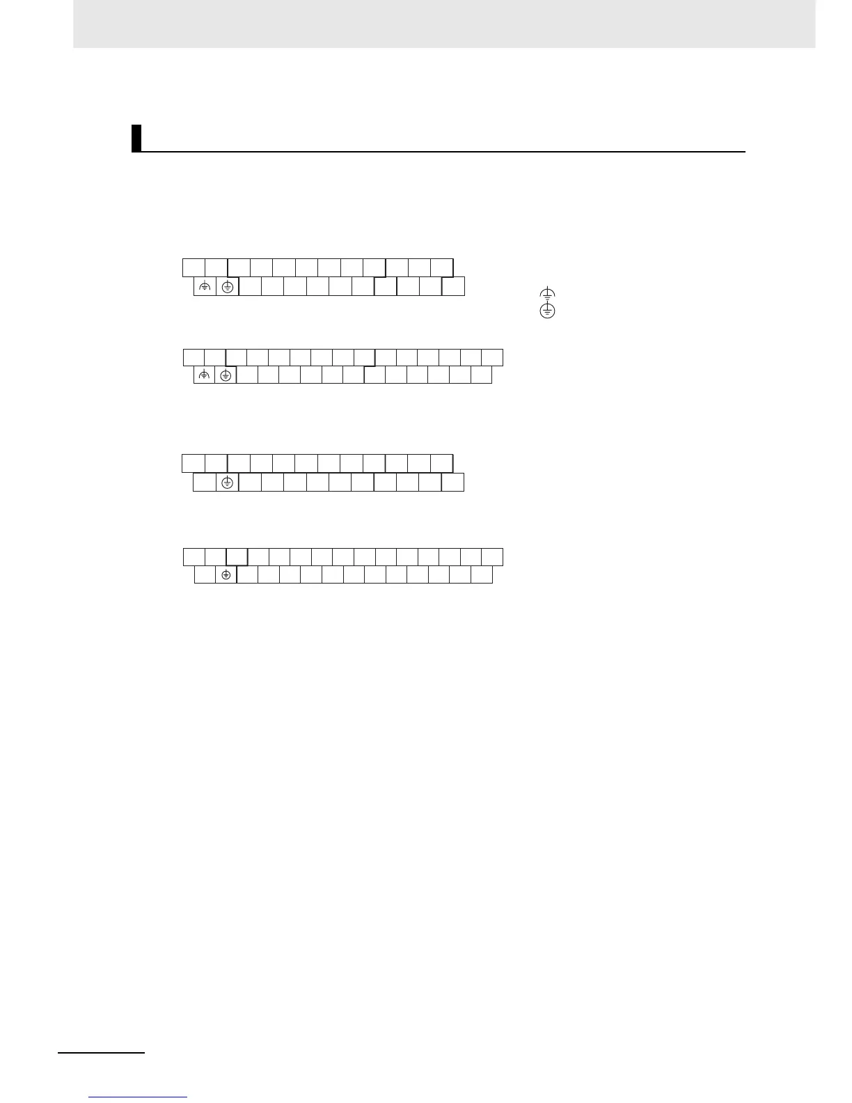
z Input Arrangement
Terminal Arrangements
AC Power Supply
CP1E-30D-A
CP1E-40D-A
DC Power Supply
CP1E-N30D-D
CP1E-N40D-D
CIO 0
CIO 1
L1 L2/N
COM
NC
01 03 05 07 09 11
00 02 04 06 08 10
01 03 05
00 02 04
L1,L2/N : Power supply terminal
: Functional ground terminal
: Protective ground terminal
COM : Common terminal
00 to 11 : Input terminal
NC : No connection
CIO 0 CIO 1
L1 L2/N
COM 01 03 05
00 02 04
07 09 11
06 08 10
01 03 05
00 02 04
07 09
11
06 08 10
CIO 0 CIO 1
+
-
COM
NC
NC
01 03 05 07 09 11
00 02 04 06 08 10
01 03 05
00 02 04
+,
-
: External supply terminal
COM : Common terminal
00 to 07 : Output terminal
CIO 0 CIO 1
01 03 05 07 09 11
04 08
01 03 05 07 09 11
0000 02
04
06
08
10
NC
+
-
02
COM
06 10

Table of Contents

Questions and Answers:

Question and Answer IconNeed help?

Do you have a question about the Omron CP1E Series and is the answer not in the manual?

Omron CP1E Series Specifications

General IconGeneral
Data Memory8K words
Pulse Output100 kHz for 2 axes
Communication PortsRS-232C, USB
MountingDIN rail mounting
Analog InputsOptional (via expansion units)
Analog OutputsOptional (via expansion units)
Expansion UnitsDigital I/O, Analog I/O, Temperature Sensor Units
Power Supply100 to 240 VAC or 24 VDC
CPU TypeVarious (E, N, and NA types)

Related product manuals