EasyManuals Logo

Omron CP1E Series User Manual

Omron CP1E Series
260 pages
To Next Page IconTo Next Page
To Previous Page IconTo Previous Page
Page #73 background imageLoading...
Page #73 background image
3-9
3 Part Names and Functions
CP1E CPU Unit Hardware User’s Manual(W479)
3-1 CPU Units
3
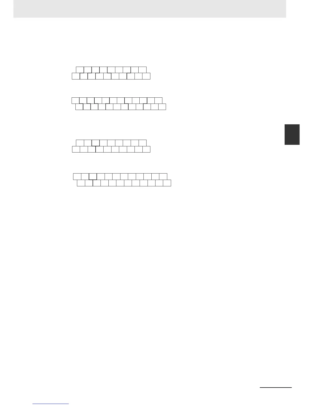
3-1-2 CPU Units with 30 or 40 I/O Points
z Output Arrangement
AC Power Supply
CP1E-30D-A
CP1E-40D-A
DC Power Supply
CP1E-N30D-D
CP1E-N40D-D
CIO 100 CIO 101
00 01 02 04 05 07 00
03 06
02
01 03
+
-
COM COMCOM COM COM
+,
-
: External supply terminal
COM : Common terminal
00 to 07 : Output terminal
CIO 100 CIO 101
+0001
07
02 03 04 06 00 01
COM COM 05 07 COM
03 04 06
02 05
COMCOMCOM
-
CIO 100 CIO 101
02
01
04 05 07 00 02
03
00
COM COM COM COM COM
NC
NC
03 06 01
+,
-
: External supply terminal
COM : Common terminal
00 to 07 : Output terminal
CIO 100 CIO 101
02
01
03 04 06 00 01 03 04 06
02
00
NC
COM COM COMCOM 07
COM
NC
05
05 07
COM

Table of Contents

Questions and Answers:

Question and Answer IconNeed help?

Do you have a question about the Omron CP1E Series and is the answer not in the manual?

Omron CP1E Series Specifications

General IconGeneral
Data Memory8K words
Pulse Output100 kHz for 2 axes
Communication PortsRS-232C, USB
MountingDIN rail mounting
Analog InputsOptional (via expansion units)
Analog OutputsOptional (via expansion units)
Expansion UnitsDigital I/O, Analog I/O, Temperature Sensor Units
Power Supply100 to 240 VAC or 24 VDC
CPU TypeVarious (E, N, and NA types)

Related product manuals