Controlling/Outputting in Parallel
FQ-CR2 User’s Manual
99
8
Communications with External Devices
• I/O Signal Allocations
The BUSY signal will remain ON while the measurement is being executed.
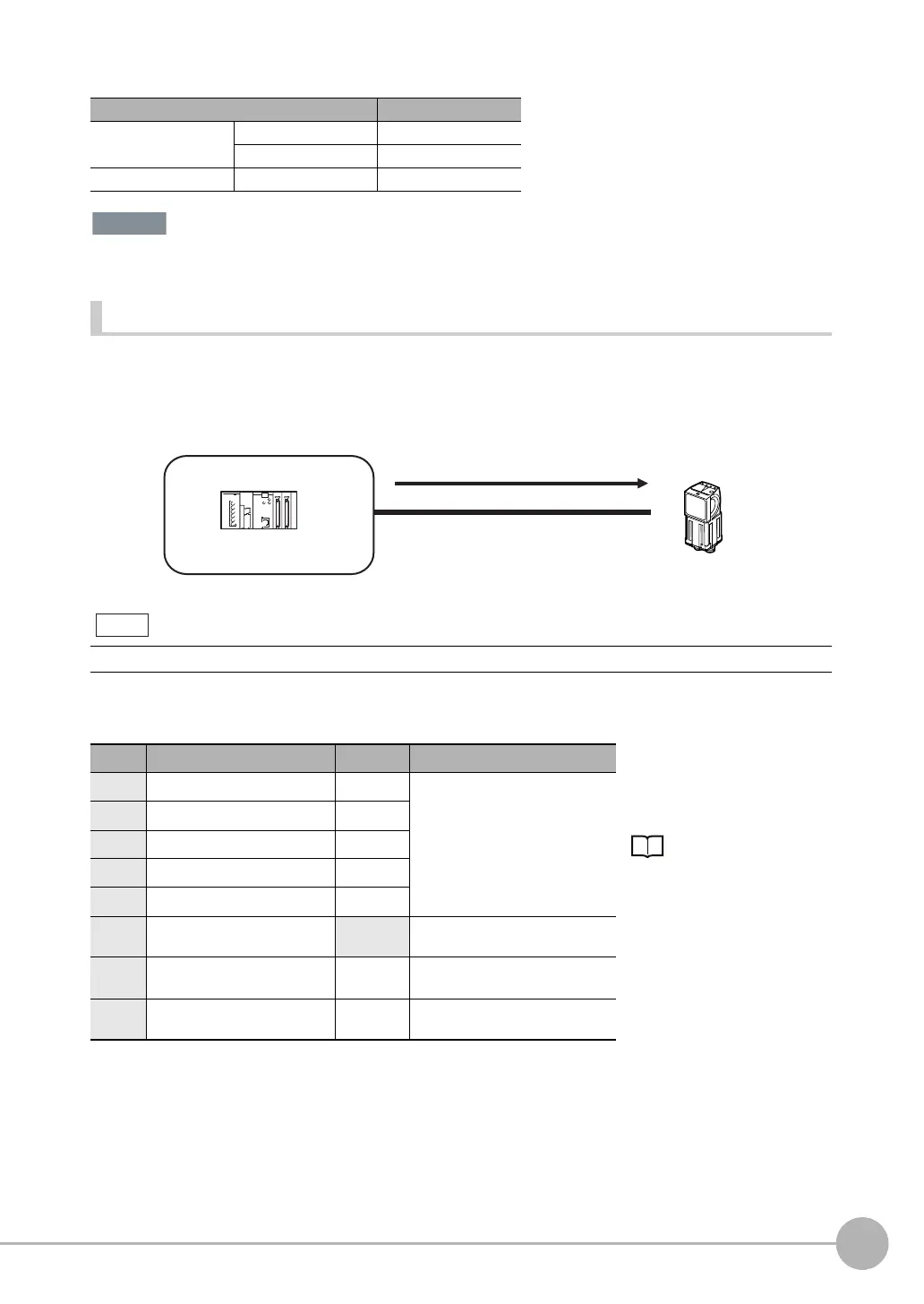
Performing Continuous Measurements
Continuous measurements are performed while the continuous measurement command is input from an
external device.
Immediately after a measurement is performed, the next measurement is performed.
This is repeated while a continuous measurement command is input with the IN0 to IN5 signals.
Wiring
Signal Address
Output signals OUT0 (OR signal) CIO 0.00
OUT1 (BUSY signal) CIO 0.01
Input signals TRIG CIO 1.00
This function can be used only when the input mode is set to Expanded Mode.
Color Signal State Description
The signals shown at the left
are used.
Refer to the following informa-
tion for signal wiring.
Wiring: p. 26
Gray IN0 OFF Command parameters for continu-
ous measurements
Green IN1 OFF
Red IN2 OFF
White IN3 OFF
Purple IN4 OFF
Ye l l o w IN5 ON Command input for continuous
measurements
Black OUT0 (OR) -- Overall judgement (default assign-
ment)
Orange OUT1 (BUSY) -- Processing in progress (default
assignment)
PLC
(2) Performs continuous
measurements
Or other
device
(1) IN5 signal ON (IN0 to IN4 are OFF)
Note
FQ Sensor User Manual.book 99 ページ 2011年7月8日 金曜日 午後2時30分