User Manual
Advanced Console Server & RIM Gateway User Manual 189
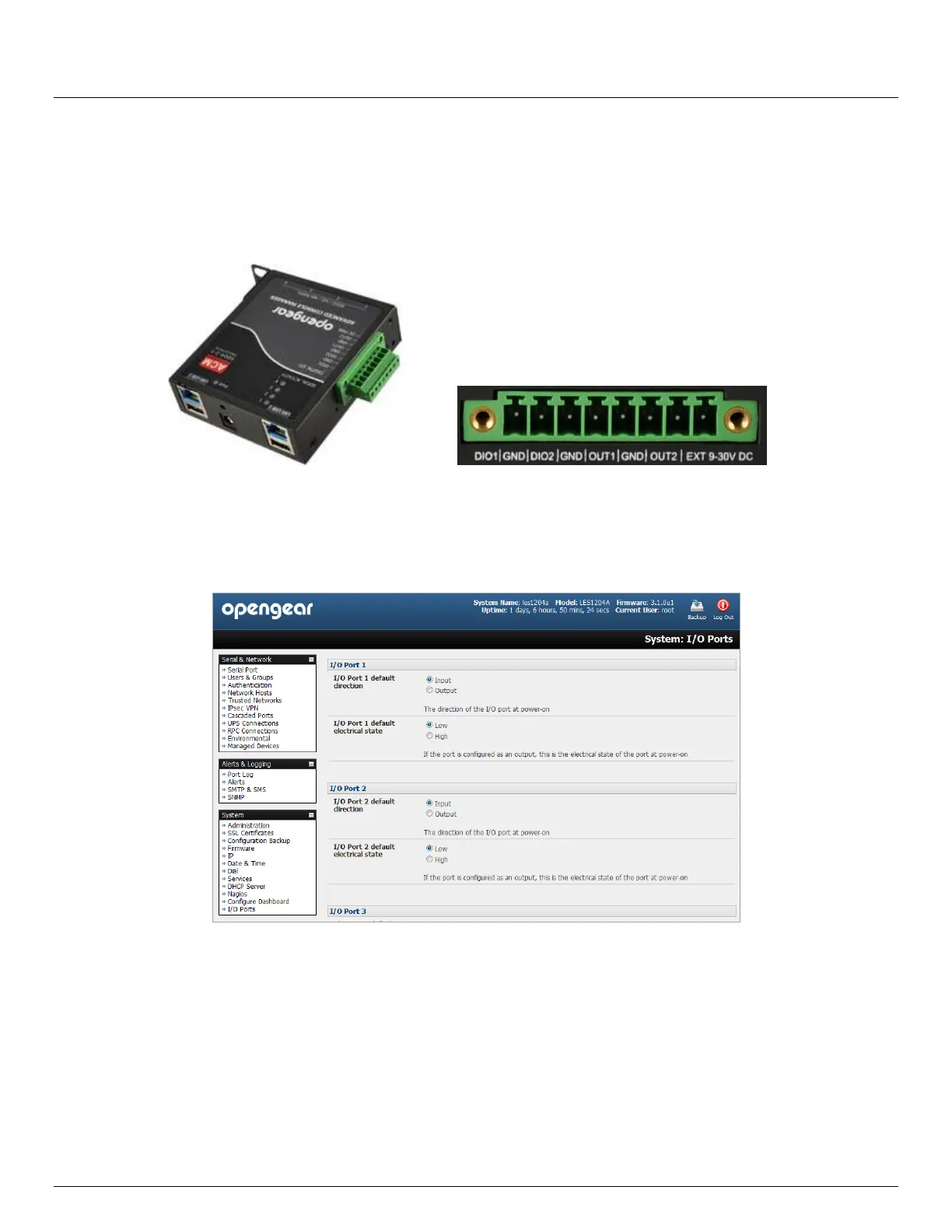
8.4 Digital I/O Ports
The ACM5004-2-I, ACM5508-2-I and ACM5504-5-G-I models have four digital interface ports which present on a green
connector block on the side of the unit:
DIO1 and DIO2 are two TTL level digital I/O ports (5V max @ 20mA)
OUT1 and OUT2 are two "High-Voltage" digital Output ports (>5V to <= 30V @100mA)
The I/O ports are configured via the I/O port page which is found under the system menu. Each port can be configured
with a default direction and state.
Select the System: I/O Ports menu
8.4.1 Digital I/O Output Configuration
Each of the two digital I/O ports (DIO1 and DIO2) can be configured as an Input or Output port. To use them as digital
outputs first configure the port direction on the System: I/O Ports menu page.
The DIO1 and DIO2 pins are current limited by the chip to 20mA and accept 5V levels – so they cannot drive a relay etc.
Alternately you can change the output states using the ioc command line utility. The following text is the usage message
from the ioc usage:
ioc: digital io-port controller:
-p pin_num pin number (1 to 4)
-d pin_dir pin direction (0 = output 1 = input)