14-36
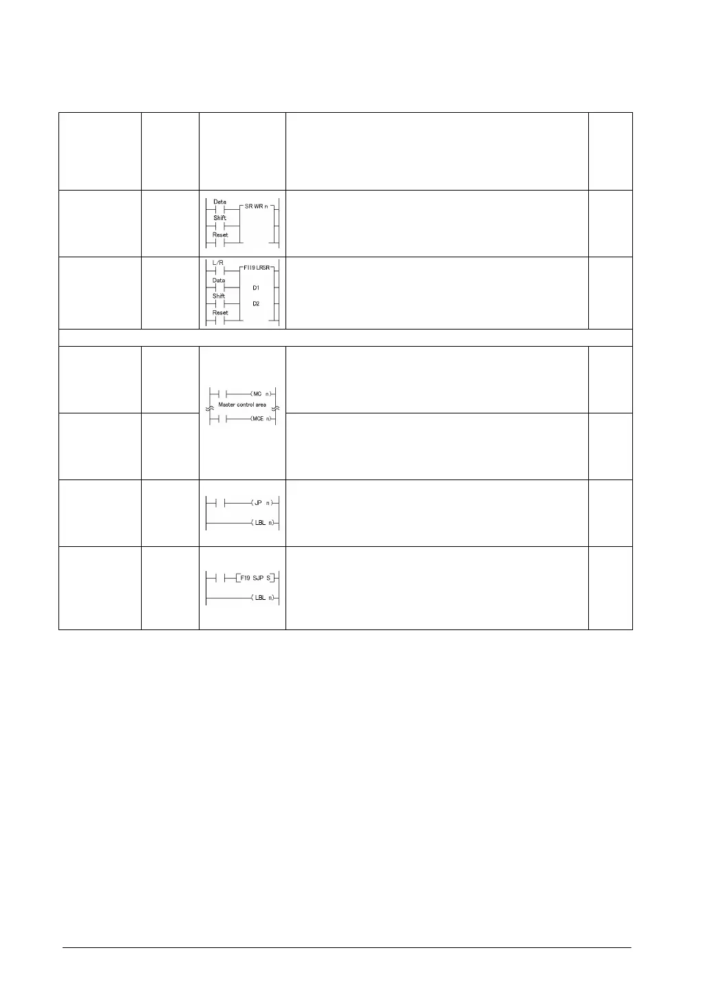
Name Boolean Symbol Description Steps
Shift register SR
Shifts one bit of 16-bit [word internal relay (WR)] data to
the left.
1 (2)
Note1)
Left/right
shift register
F119
(LRSR)
Shifts one bit of 16-bit data range specified by “D1” and
“D2” to the left or to the right.
5
Control instructions
Master
control relay
MC
Starts the master control program. 2
Master
control relay
end
MCE
Ends the master control program. 2
Jump
Label
JP
LBL
The program jumps to the label instruction and continues
from there.
2 (3)
Note2)
1
Auxiliary
jump
Label
F19
(SJP)
LBL
The program jumps to the label instruction specified by “S”
and continues from there.
3
1
*1) In the FP2/FP2SH/FP10SH, when internal relay WR240 or higher is used, the number of steps is the
number in parentheses. Also, in the FP2/FP2SH/FP10SH, when the specified internal relay number
(word address) has an index modifier, the number of steps is the number in parentheses.
*2) In the FP2/FP2SH/FP10SH, when the number “n” in a jump instruction has an index modifier, the
number of steps is the number in parentheses.