158
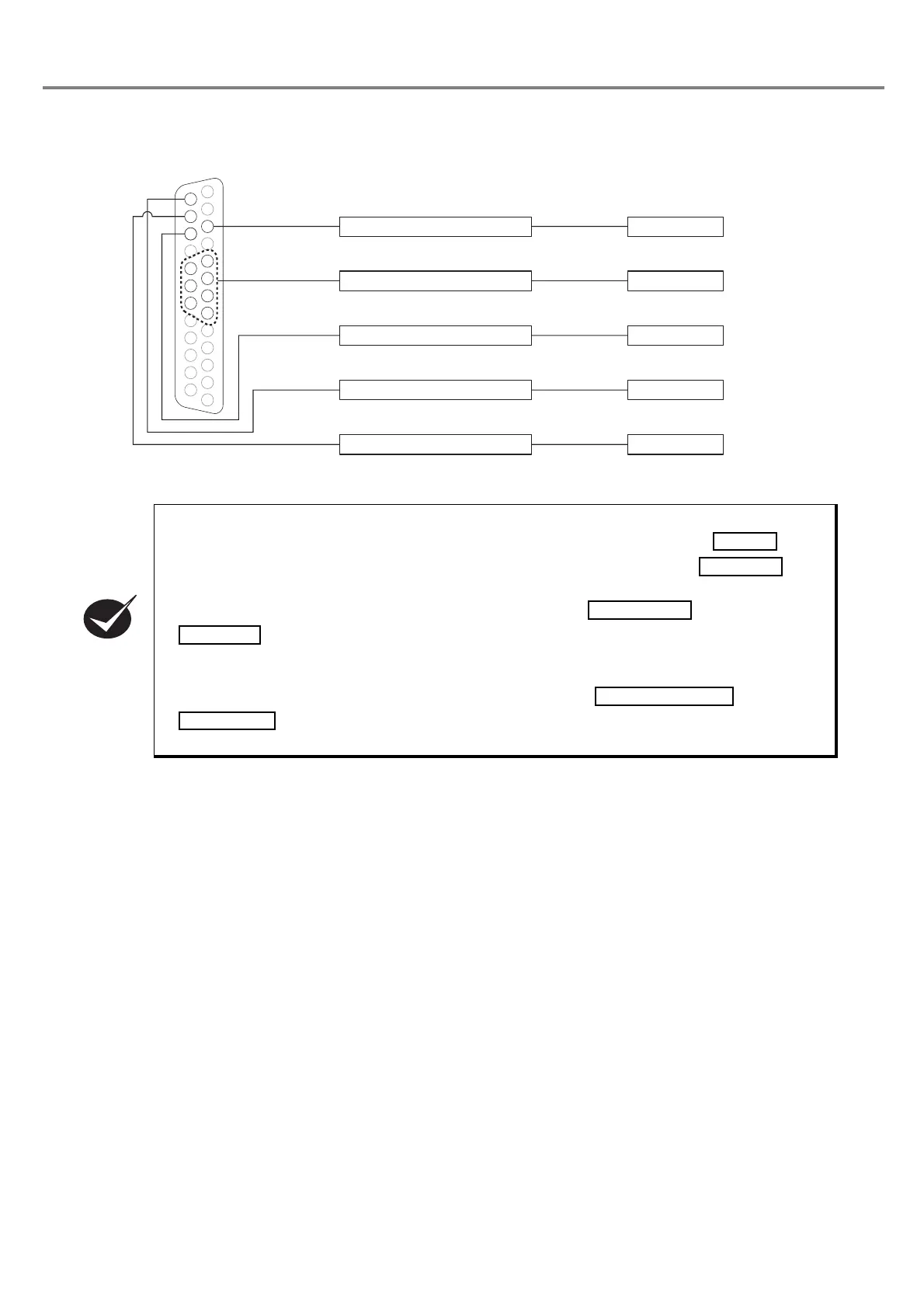
■ Connecting Sample with External Devices
• When connecting to the external devices, the laser marker is not activated unless connecting
the + (positive) side of the external power supply to the
I/O connectors
No. 14
and
connecting the ON of the external power supply to the
I/O connector
No. 15 .
For
operating the laser marker, connect the external power supply.
•
When performing marking, connect the I/O connectors No. 4
and No. 15
.
When setting the state between No. 4 and No. 15 into OPEN, the laser radiation is activated, and
the marking becomes invalid.
• When performing marking, connect the
I/O connector
s No. 1 and No. 3
. When setting the state between No. 1 and No. 3 into OPEN, the emergency stop
is activated and the marking becomes invalid.
㻝㻤
㻝㻥
䠑
䠒
䠓
䠔
㻞㻜
㻝㻠
㻝㻡
㻝㻢
䠏
3. TRIG. IN
24V
0V
5〜8, 18〜 20: D0〜D6
14. IN COM.
16. READY
15. OUT COM.
PLC
I/O Connector
Output
Output
Input