EasyManua.ls Logo

Panasonic LP-310 User Manual

Panasonic LP-310
216 pages
To Next Page IconTo Next Page
Page #1 background imageLoading...
Page #1 background image
表紙~はじめに
CO2 Laser Marker
LP-300 SERIES
Operation Manual
panasonic.net/id/pidsx/global
2018.5
ME-LP300-OP-12 No.9000-0062-20V

Table of Contents

Question and Answer IconNeed help?

Do you have a question about the Panasonic LP-310 and is the answer not in the manual?

Panasonic LP-310 Specifications

General IconGeneral
Input Voltage100-240 VAC
Frequency50/60 Hz
Output Voltage24 VDC
ProtectionOverload, Overvoltage, Short Circuit
Efficiency85%
Storage Temperature-20°C to +85°C

Summary

General Terms and Conditions

Product Warranties and Exclusions

Details product warranty, exclusions, and disclaimers.

Cautions for Safe Use

Advises on safe usage and application suitability according to local laws.

Warranty of Product

Warranty Period and Limitations

Specifies the warranty period and reasons for voidance.

Cautions in Handling Laser Beam

Laser Radiation Range Specifications

Provides specifications and diagrams for laser radiation range.

Safety Protection Measures

Interlock System and Goggles

Details on constructing interlock systems and wearing protective goggles.

Protective Enclosure and Key Control

Requirements for enclosures and using key switches for safety.

Power Supply BOX Components

Power Supply Display and Key Switch

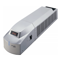
Describes the power indicator and the system's key switch.

Interlock Connector Functionality

Details the interlock connector for building system interlocks.

I/O Connector Details

Laser Radiation Stop Input and Connection Sample

Explains laser stop input and shows connection for standalone operation.

Interlock System and Operation

Interlock System Construction Sample

Illustrates a typical interlock system setup.

Interlock Input Operation States

Explains system behavior based on interlock input states.

Cautions in Handling

System Handling and Safety Warnings

General handling warnings, laser beam contact, and disassembly.

Operational and Environmental Cautions

Component and Data Management Cautions

Applicable Standards and Additional Cautions

1 Preparation

Package Contents Verification

Guide to verify all packed items are present.

System Installation and Connection

Covers system installation and connecting components/external devices.

Package Check Details

Checking Delivered Items

Details how to check the contents of the product package.

Laser Marker Installation

Physical Installation Method

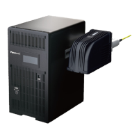
Provides instructions on how to physically install the head and power supply.

Useful Installation Functions

Connecting Laser Marker Components

Connecting Head and Power Supply BOX

Step-by-step guide to connect the head and power supply.

Connecting to Personal Computer

Instructions for connecting the laser marker to a PC via USB.

External Device Connection

External Control Connection Samples

Shows examples of connecting for external control via I/O or RS-232C.

External Control Operation

External Control Operation Flow Chart

Outlines the steps for external control operation.

Switching to Remote Mode

Procedure to Enter Remote Mode

How to switch the marker to remote mode for external control.

2 Basic Operation Procedure

First-Time Laser Marker Usage

Guide for initial setup and operation of the laser marker.

Basic Function Setting Procedures

Steps for configuring basic functions.

Initial Laser Marker Operation

Laser Marker Operation Preparation

Steps for Preparing Operation

Details steps for preparing the laser marker for operation.

Laser Marker Startup Procedure

System Startup Steps

Instructions for starting up the laser marker system.

Marking Condition Setup

Setting Marking Conditions

Details on setting character height, width, and position.

Laser Setting for Marking

Setting Laser Power and Scan Speed

Procedure for setting laser power and scan speed.

Test Marking Execution

Settings and Power Management

Turning Off Laser Marker Power

Steps to safely turn off the laser marker.

Basic Function Settings

Setting the Mark Counter Function

Guide to setting up the mark counter function.

Counter Setting Procedure

Setting Counter Values

Steps to set initial, end, and step values for the counter.

Counter Function Character Input

Inputting Counter Function Characters

How to input the counter's functional character string.

Lot Number Marking

Lot Function Character Input

Expiry Date Marking

Expiry Date Function Character Input

Current Date Marking

3 Description of Operation Screen

Main Screen Layout

Operation Screen Features Summary

Main Screen Construction

Software Menu Functions

Software Modes and Utilities

Toolbar Functions

File Selection Management

Registration File Management

Opening Registration Files

Saving Marking Files

3-3 Character Setting

Inputting Marking Characters

Inputting Function Characters

Inputting Current Date Function

Setting up the function to mark the current date and time.

Inputting Expiry Date

Function for Marking Expiry Date

Function for marking expiry date based on current date.

Inputting Optional Character String

Inputting Registration Character

3-4 Function Setting

Function Setting Screen Overview

Interface for setting expiry, counter, and lot functions.

Expiry Date Function Settings

Configuring Expiry Date Calculation

Configuring the expiry date calculation.

Counter Function Settings

Setting Counter Initial, End, and Step Values

Setting initial, end, and step values for the counter.

Lot Function Settings

Setting Lot Marking Parameters

Setting lot marking based on periods and characters.

3-5 Marking Condition

Character Condition Settings

Marking Shape Character Settings

Tilted Marking Shape

Fan Like Marking Shape

Character Stroke and Laser Adjustments

3-5-4 CAD Condition

CAD File Management

Font and Size Settings

Graphic Offset and Laser Adjustments

Laser Check Procedure

Performing Laser Beam Check

Procedures and conditions for performing a laser check.

3-6 Laser Setting

Laser Stroke Adjustments

Laser Start/End Point Adjustment

Marking Quality Adjustment

3-7 Image Display

Image Magnification Methods

Marking Position Adjustment

3-8 Guide Indication

3-9 Test Marking

Performing Test Marking

Steps for performing test marking from PC.

Test Marking Process Details

3-10 Send/Read Operations

File Transmit Procedure

Transferring marking files to the laser marker.

File Transfer Process Management

File Management Operations

Restore Marking Data

3-11 PC Control/Remote Mode

Remote Mode Setup and Usage

Setting and using the remote control mode.

Switching to PC Control Mode

PC Control Mode Operation

Setting and Using PC Control Mode

Setting and using the PC control mode.

3-13 Error History

Environmental Settings

Laser Marker Communication Settings

Font File Management

4 External Control

Control Through I/O Connector

Controlling the laser marker via the I/O connector.

Control via RS-232C Communication

Controlling the laser marker via RS-232C serial communication.

I/O Connector Control Preparation

External Device Connection Samples

I/O Connector Signal Information

I/O Connector Signal Names and Contents

Details of I/O connector signals and their functions.

Input Signal Specifications

Output Signal Specifications

I/O Input/Output Operations

I/O Connector Input Signal Operations

Detailed explanation of I/O input signals.

I/O Output Signals and Power

I/O Connector Output Signal Details

Detailed explanation of I/O output signals.

Basic I/O Timing Chart

4-2 Control with RS-232C

RS-232C Interface Details

RS-232C Communication Settings

Configuring Communication Parameters

Configuring communication parameters for RS-232C.

RS-232C Connection Check

Verifying RS-232C Connection

Steps to verify the RS-232C connection.

RS-232C Control Samples

RS-232C Control Sample 1

RS-232C Control Sample 2

Communication Data Formats

Command Data Format

Format for commands sent to the laser marker.

Response Data Formats

Normal and Abnormal Response Data

Types and formats of responses from the laser marker.

Abnormal Response Data

Readout Response Data

Communication Sequences

Marking Status Transmission Control

Command Transfer and Control Methods

4-2-10 Communication Commands

List of Communication Commands

Lists available communication commands and their functions.

Detailed Command Explanations

Detailed explanations of specific commands.

File Number Change Command

Arbitrary Character String Commands

Setting and Reading Arbitrary Strings

Commands for setting and reading arbitrary character strings.

Counter Value and Reset Commands

Counter Value Setting and Readout

Commands for setting and reading the current counter value.

Counter Reset Command

Command to reset the counter to its initial value.

Status Request and Marking Trigger

Status Request Command

Command to read the laser marker's operation status.

Marking Trigger Command

Command to trigger marking.

Marking Status Transmission Commands

Marking Status Transmission Permission

Setting response permission for marking status.

5 Troubleshooting

General Troubleshooting Guide

General guide for resolving operational errors.

Measures for Indicated Errors

Solutions for specific error codes displayed by the marker.

Troubleshooting Common Issues

Troubleshooting Table

Table of common troubles, causes, and measures.

Indicated Error Measures

Error Code Explanations and Remedies

Detailed explanation of error codes and their remedies.

Error Display and I/O Output Correlation

6 Maintenance

General Maintenance Information

General information on maintaining the laser marker.

Maintenance Procedures

7 Specification

Technical Specifications

Detailed technical specifications of the laser marker.

Detailed Technical Specifications

Laser Marker Specifications

Detailed technical specs including laser type, power, and environment limits.

Related product manuals