123
• Origin position specification
This item specifies which part of a graphic is aligned to the origin (0, 0) of the coordinate system.
The whole graphic is shifted so that the specified part is aligned to the position of the origin.
The following 6 types origin can be specified.
“Center” “Left Down” “Right Down”
“Left Up” “Right Up” “Same”
• X/Y Position
Move the original position of the CAD file data in the X and Y directions for the X and Y positions respec-
tively.
Setting Range: -25.00 to +25.00mm
• Rotation Angle
Rotate the CAD file data around the original position. The counterclockwise direction is the forward direc-
tion.
Setting Range: -180.0 to +180.0 °
(4) Laser Power Revise and Scan Speed Revise
“Remain the original graphic” means that the position of the read-in original CAD data is not
changed.
Some graphics cannot be marked as displayed in the image display if a DXF file created by
AutoCAD is read in by the setting software.
Refer to “Readable DXF File” (P.207) for details of the correspondence table between the LP-310
setting software and the drawing function of AutoCad.
• Laser Power Revise :
Adds the correction to the laser power of the setting line.
Setting Range: 0 to 200%
• Scan Speed Revise :
Adds the correction to the scan speed of the setting line.
Setting Range: 50 to 200%
• If the value of the laser power correction multiplied by the laser power is 100 or more, the “100”
is applied as the correction value.
• If the value of the scan speed correction multiplied by the scan speed is 2000mm/s or more, the
“2000mm/s” is applied as the correction value.
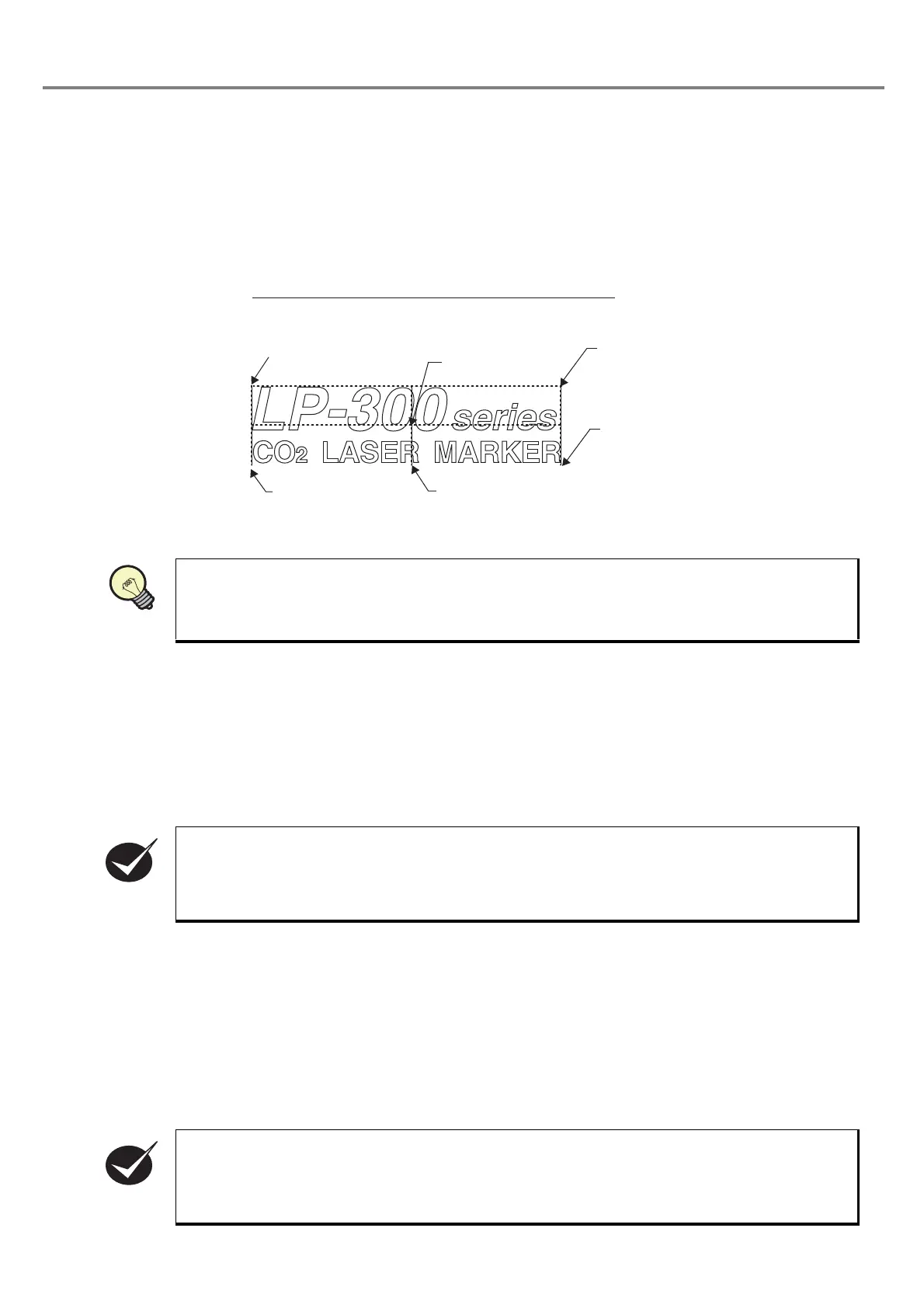
Bottom left of graphic
(Left Down)
Center of graphic
(Center)
Conceptual Diagram Showing each Origin Position
Top right of
graphic
(Right Up)
Top left of graphic
(Left Up)
[Circumscribed rectangle and center line]
Bottom right of
graphic
(Right Down)
REFERENC