157
4-1-2
I/O Connector
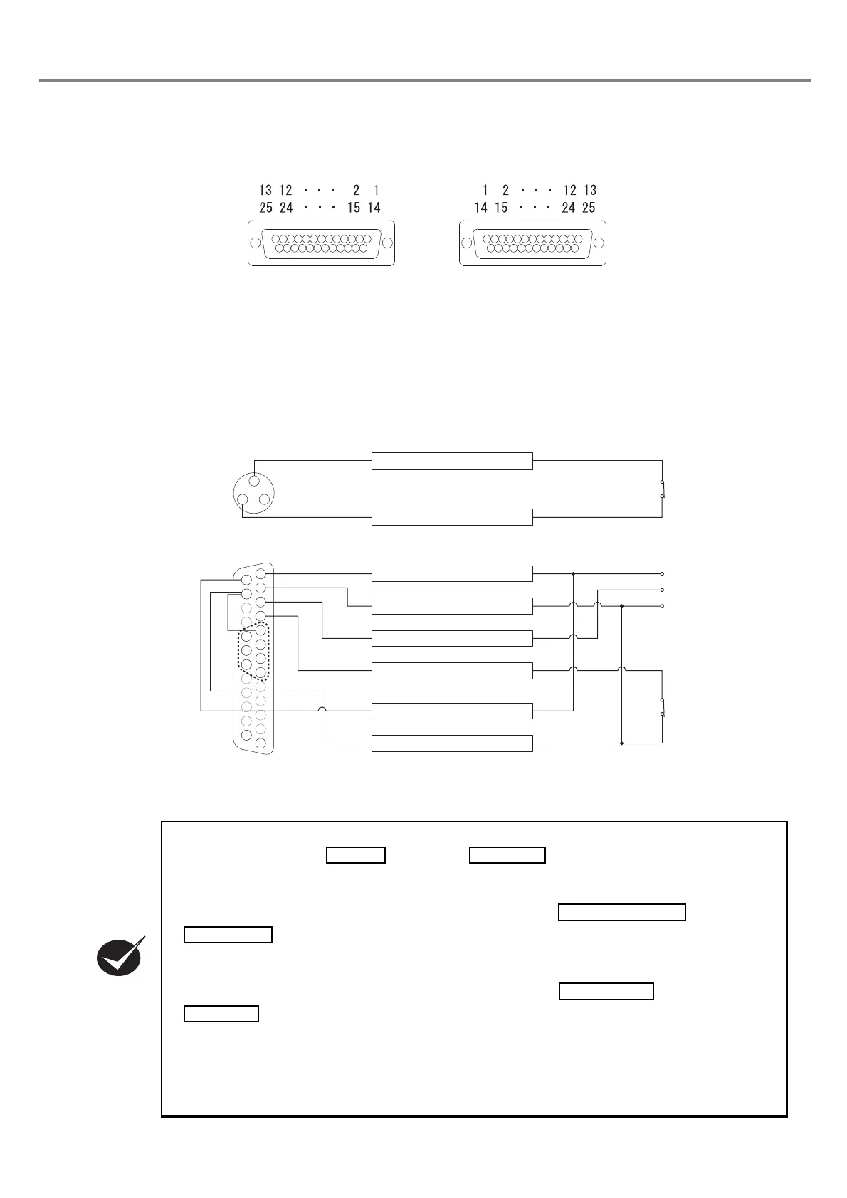
■ Appearance of Connector
Laser Marker Side Connector Type : Female D-sub 25 pin
User Side Connector Type : Male D-sub 25 pin *
*As a user side connector, following items are attached to this product.
[Attached item] User Side Connector : HDBB-25P (Hirose Electoric Co., Ltd.)
[Attached item] User Side Connector Cover : HDB-CTF (Hirose Electoric Co., Ltd.)
■ Connecting Sample (In case of operating laser marker standalone)
* Example when only the file No. 1 is used. To change the files, connect the pin No. 5 to 8 and 18 to 20 (D0 to D6)
to the external control device.
• If not connecting the power supply (either internal power supply or external power supply) to the
I/O connectors No. 14
and No. 15 , the laser marker is not activated.
For activating the laser marker, connect the power supply (either internal power supply or external
power supply).
• When performing marking, connect the
I/O connector
No. 1 and No. 3
.
When setting the state between No. 1 and No. 3 into OPEN, the emergency stop is
activated and the marking becomes invalid.
Be sure to connect the interlock terminals on the connecting point.
(24V 500mA)
•
When performing marking, connect the I/O connectors No. 4
and No. 15
.
When setting the state between No. 4 and No. 15 into OPEN, the laser radiation is activated, and
the marking becomes invalid.
• When the interlock is short-circuited from OPEN, the head panel is displayed rotationally.
While the head panel is displayed rotationally, the marking ready READY becomes OFF, and
the laser marker does not perform marking.
Laser Marker side User side
㸨
䠍
䠍
㻟 㻞
㻝㻠
㻝㻡
㻝㻤
㻝㻥
㻞㻜
㻞㻡
㻝㻟
䠏
䠎
䠐
㻡
㻣
㻢
㻤
1. INTERLOCK COM.
3. INTERLOCK
1. +12V
2. 0V
3. TRIG. IN
4. LASER STOP
14. IN COM.
15. OUT COM.
Interlock Input Terminal
(Power Supply BOX)
To Emergency
Stop Switch
I/O Connector
To Sensor
To Manual Door
0V
12V
CHECK