40
1-4 Connecting Laser Marker
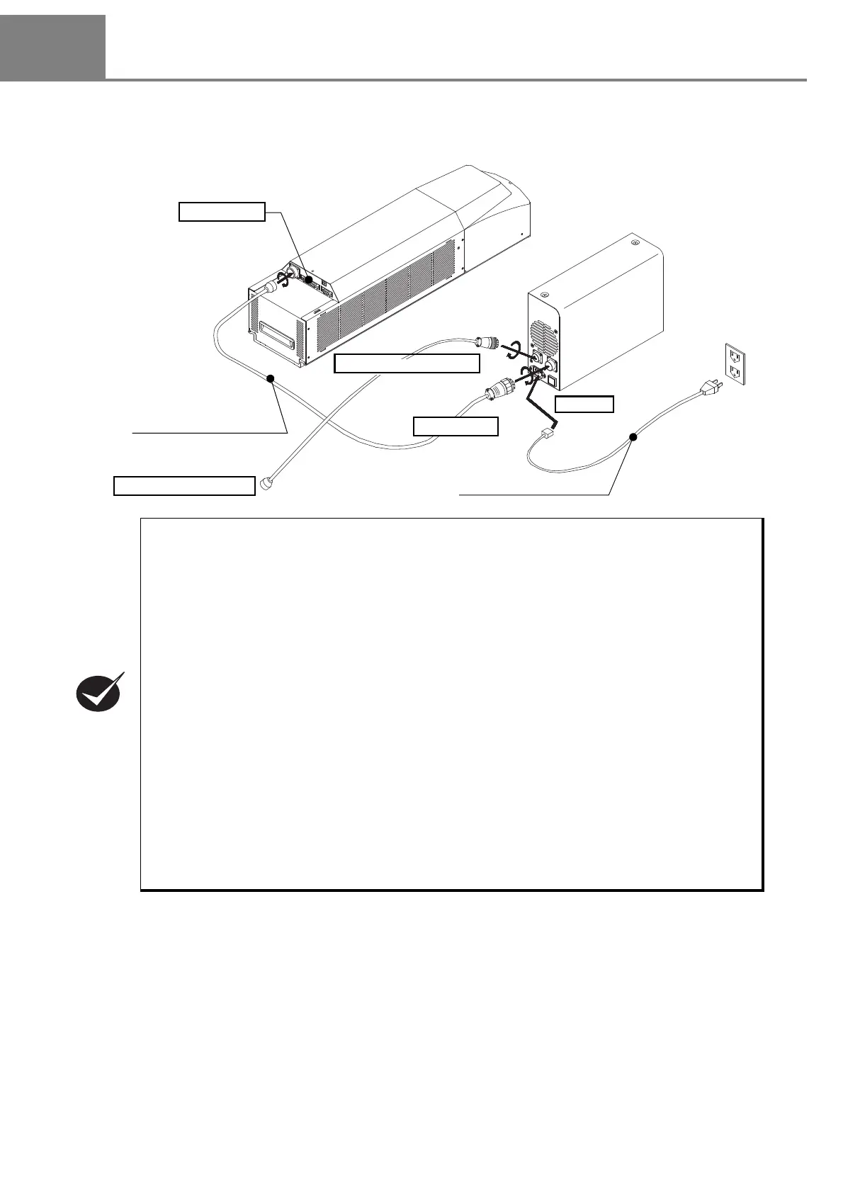
1-4-1 Connecting Head and Power Supply BOX
Connect the following items using the attached specific cables.
• Connect the items above using the attached specific cables.
• For the connectors location, refer to “1-2-1 Head” (P.34) and “1-2-2 Power Supply BOX” (P.35).
• Attached AC power cable varies depending on each model. Please select a cable suitable for
the standards in the country or region where it is used.
1. Perform the connection of the AC power at the end. Do not insert or pull cable with the power
in supplied state.
2. Pay attention to the power source so as not to occur noise with enough.
3. Set each connecting cable away from the device that generates high voltage, power line, and
large switching surge as far as possible.
4.
If any noise is occurred on the power source, use the noise cut-off transducer.
5. Be sure to ground the F.G. (frame ground) terminal. Refer to “1-2-2 Power Supply BOX” (P.35)
for the terminal position.
6. Fix the connector with screws securely so as not to drop it.
7. To operate this laser marker, connect the following signals on I/O connector. For the details,
refer to “4-1-2 I/O Connector” (P.157).
• Connect the power supply to [IN COM.] (pin No.14) and to [OUT COM.] (pin No.15) respectively.
• Connect [LASER STOP] (pin No.4) and [OUT COM.] (pin No.15) to release the erroneous irradiation
prevention function for the laser.
Head
Power Supply BOX
Head Power Cable (5m)
To POWER
To Inle t
To Interlock Connector
To Interlock System
AC Power Cable (5m)
Wiring of I/O