159
4-1-3
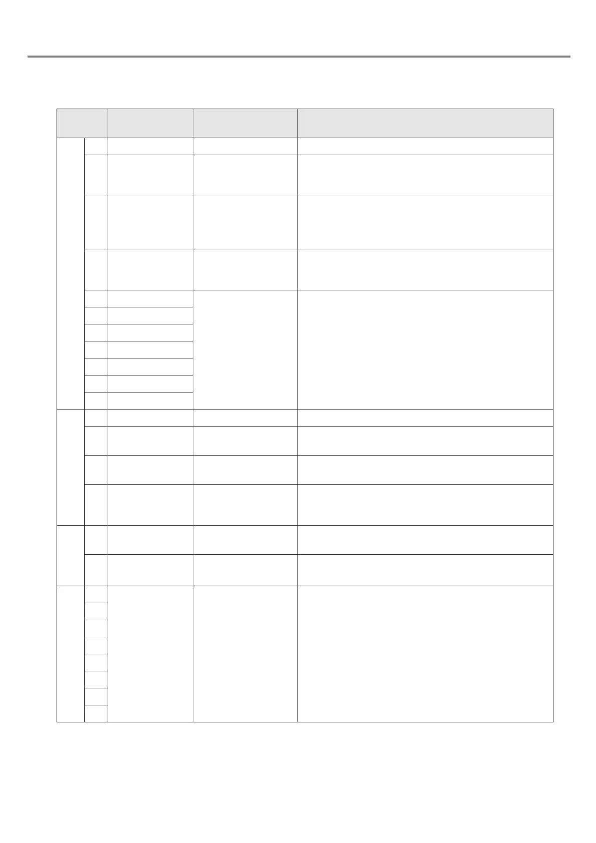
Signal Name and Content of I/O Connector
Terminal
No.
Display Name Description
14 IN COM. Input common Common for input
3 TRIG. IN Trigger input
Starts marking on the edge of the input ON.
Input TRIG. IN with holding the input status of the file
selection (D0 to D6).
4 LASER STOP
Laser radiation stop
input
When setting the states of both
I/O connector
s No. 4
LASER STOP and No. 15 OUT COM. to OPEN, the
laser radiation is stopped. For marking, short-circuit the
terminals No. 4 and No. 15.
17
COUNTER
RESET
Counter reset input
Sets this terminal ON for resetting the counter.
Input COUNTER RESET with holding the input status of
the file selection (D0 to D6).
5D0
File select input
These terminals are used for switching the file No. 1 to
No. 120 saved in the head. Keep the input status of D0
to D6 while using the selected file.
18 D1
6D2
19 D3
7D4
20 D5
8D6
15 OUT COM. Output common Common for output
16 READY Marking ready output
When the marking is ready for starting (in TRIG.IN input
receivable state), the output becomes ON.
25 COUNTER END Counter reset output
When the counter reaches to the ending value, the output
comes ON.
13 ALARM Alarm output
When an alarm is occurred, the output becomes OFF.
The content of the alarm is displayed with error code in
the head display panel.
1+12V
Power supply for
external device +12V
+12V DC power supply for external device. (100mA Max.)
20V
Power supply for
external device 0V
Ground for the power supply for external device (common
to the inside)
9
Reserved System reserve Do not connect anything to the external devices.
10
11
12
21
22
23
24