14
■ Construction Sample of Interlock System
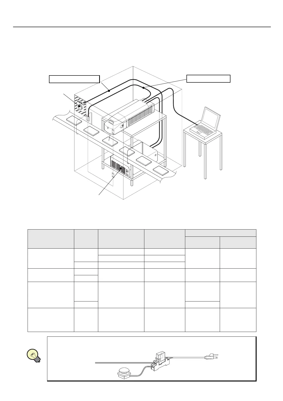
• For operating this product, construct the protective enclosure enclosing the range of the laser radiation for
protecting the exposure caused by the reflection of the laser radiation from the object being marked or the
surrounding objects, and also construct the interlock system at the same time. The following figure shows
the construction sample of the interlock system.
■ Operation at Interlock Input
As shown in the table below, this product outputs error state by canceling the interlock input and also stops the
laser oscillation aiming for safety use of this product.
Status of
Interlock Input
Shutter
Laser Oscillation
(Marking
Operation)
Laser Radiation
Indicator
Laser Marker
Status
Head display
panel
Short-circuit
OPEN
ON Red
Normal
Operation
File No.OFF Blue
CLOSE OFF Blue
Release
OPEN
OFF Blue Alarm Status Error Code
CLOSE
Release
↓
Short-circuit
OPEN
OFF Blue
Ready OFF
↓
after 15 sec.
Ready ON
Error Code
↓
after 15 sec.
File No.
CLOSE Ready OFF
Short-circuit
↓
Release
(Releasing during
marking operation)
OPEN
ON
↓
OFF
Red
↓
Blue
Normal
↓
Alarm Status
File No.
↓
Error Code
•
When primary AC power supply of the system is performed as a safety measure, process AC
power cable to set the switch as follows.
Power Supply BOX
To Interlock Connector
I/O Connector at Head
To Laser Stop Input
Emergency Stop
Switch
Power Supply BOX
PC
Relay
Emergency Stop Switch
AC Power Cable