13
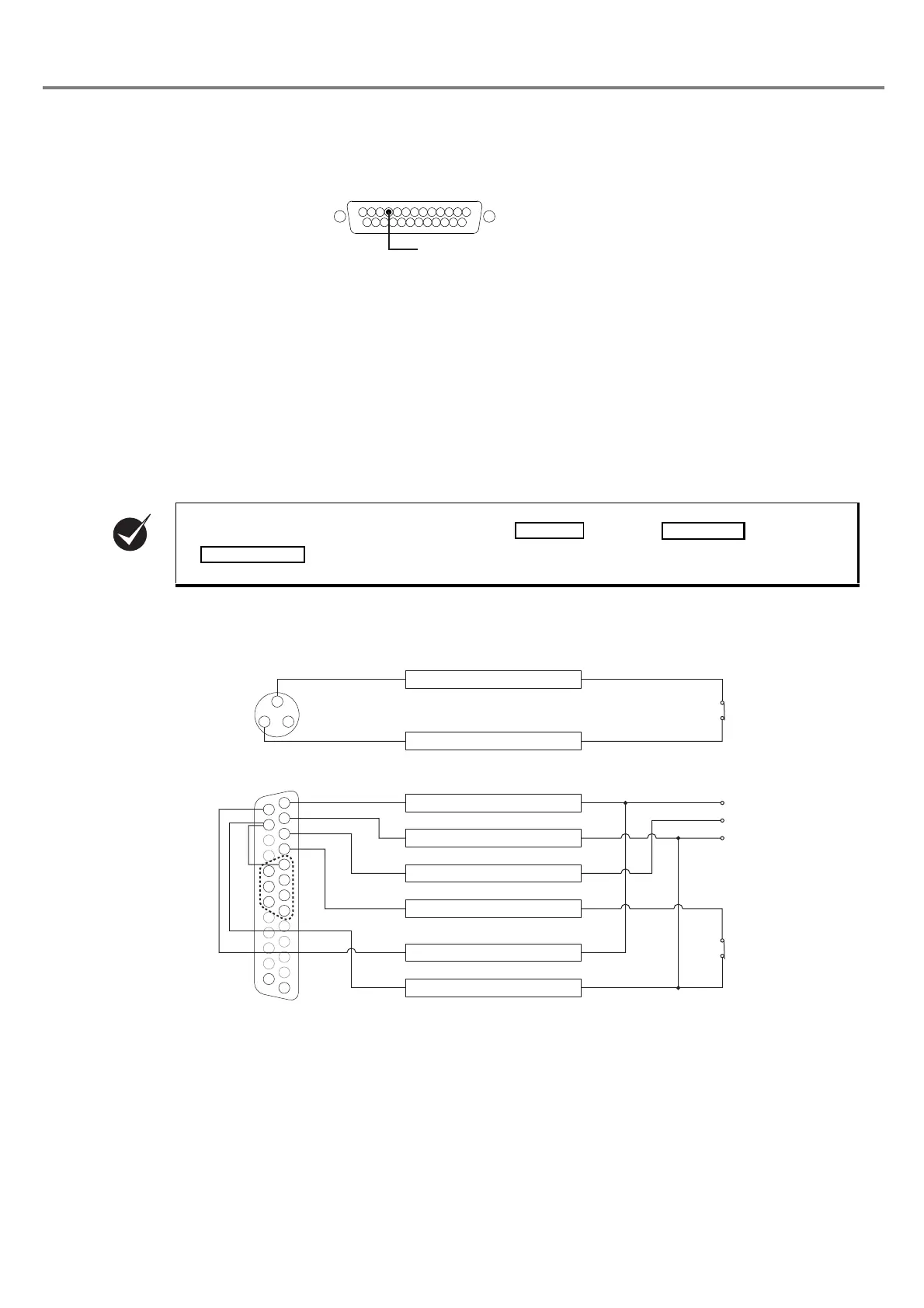
■ I/O Connector
• This product is equipped with the laser radiation stop input in the I/O connector.
Laser Marker Side Connector Type : Female D-sub 25 pin
User Side Connector Type : Male D-sub 25 pin *
* As a user side connector, following items are attached to this product.
[Attached item] User Side Connector : HDBB-25P (Hirose Electoric Co., Ltd.)
[Attached item] User Side Connector Cover : HDB-CTF (Hirose Electoric Co., Ltd.)
Laser Radiation Stop Input
• When changing the status of both laser radiation stop input (Pin 4) and output common (Pin 15) into open
status, the laser radiation is stopped and the marking is invalid.
When performing marking, connect both laser radiation stop input (Pin 4) and output common (Pin 15).
■ Connecting Sample (In case of operating only laser marker)
* Example when only the file No. 1 is used. To change the files, connect the pin No. 5 to 8 and 18 to 20 (D0 to D6) to the
external control device.
• This product is not activated by connecting (Pin 14), (Pin 15), and
(Pin 4) terminals of the I/O connector.
Laser Radiation Stop Input
Pin 4
㸨
䠍
䠍
㻟 㻞
㻝㻠
㻝㻡
㻝㻤
㻝㻥
㻞㻜
㻞㻡
㻝㻟
䠏
䠎
䠐
㻡
㻣
㻢
㻤
1. INTERLOCK COM.
3. INTERLOCK
1. +12V
2. 0V
3. TRIG. IN
4. LASER STOP
14. IN COM.
15. OUT COM.
Interlock Input Terminal
(Power Supply BOX)
To Emergency
Stop Switch
I/O Connector
To Sensor
To Manual Door
0V
12V