163
(E.g.) In case of specifying the marking file No. 50 transferred into the head:
• Since the “50” is represented as “0110010” with binary digit, set the value of the lowest digit as “D0”, and
select ON/OFF as follows.
■ I/O Connector Output Signal
Terminal No. 15: Output Common (OUT COM.)
•
This is the terminal for output common.
Connect this terminal to the “+” (plus) side of the control power
supply for NPN connection, and connect this terminal to the “-” (minus) side of the control power supply
for PNP connection.
Terminal No. 16: Marking Ready Output (READY)
• This is the terminal for marking ready output. When the marking is ready for starting (with TRIG.IN input
receivable state), the output becomes ON.
Terminal No. 25: Counter Ending Output (COUNTER END)
•
When the counter reaches to the ending value, the output comes ON. The counter ending output continues
until the next marking start input is entered.
Terminal No. 13: Alarm Output (ALARM)
・When an alarm is occurred, the output becomes OFF. The laser radiation stops when this alarm output
becomes ON.
The content of the alarm is displayed with error code in the head display panel.
■ I/O Connector Power Supply
Terminal No. 1: Power Supply for External Device +12V (+12V)
• This is the power supply for external device. The max. output current is 100mA.
Terminal No. 2: Power Supply for External Device 0V (0V)
• This is the 0V power supply for external device.
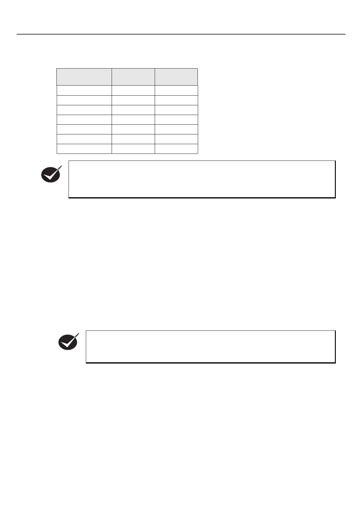
Termina l
(Terminal No.)
Binary Digit Input
D0 (No. 5) 0 OFF
D1 (No. 18) 1 ON
D2 (No. 6) 0 OFF
D3 (No. 19) 0 OFF
D4 (No. 7) 1 ON
D5 (No. 20) 1 ON
D6 (No. 8) 0 OFF
• Keep the input status of D0 to D6 while using the selected file. TRIG. IN and COUNTER RESET
are executed to the selecting file number by D0 to D6 input.
• Once the file No. changing command (FNO) is set by RS-232C, changing files by D0 to D6
input of I/O connector is not available.
• The counter is not activated for the test marking.
• The counter ending output continues until the next marking start input is entered.
CHECK