1-106 Programming Your Application
690+ Series Frequency Inverter
Functional Description
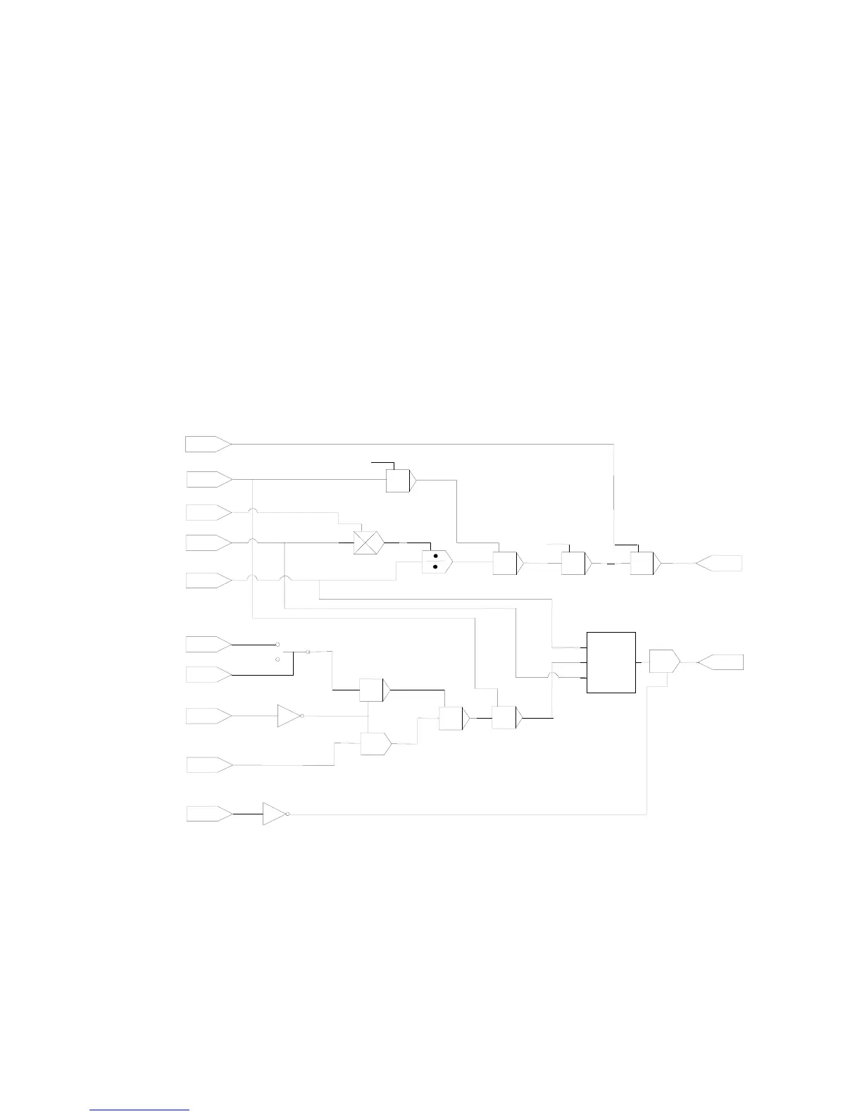
The speed demand calculator takes its reference from the line speed setpoint.
The polarity is determined by OVER-WIND , this is positive for Over (OVER-WIND = TRUE).
REWIND
OVER WIND
DIAMETER
MINIMUM DIAMETER
SPEED TRIM
LINE SPEED
OVER SPEED
SPEED DEMAND
+
chs
+
z
u
1
y
x
xy/z
chs
MOD REEL SPEED
-
|X| >
UTS THRESHOLD
0
OVER SPD ENABLE
chs
UP TO SPEED (UTS)
|X|
Parameter Descriptions
SPEED TRIM
Range: -100.00 to 110.00 %
An additional speed loop input.
SPEED DEMAND
Range: —.00 %
The speed demand output.
UP TO SPD (UTS)
Range: FALSE / TRUE
The up-to-speed detector compares LINE SPEED with MOD REEL SPEED multiplied by
DIAMETER. When they are the same, within the UTS THRESHOLD, then UP TO SPD
(UTS) is TRUE.

 Loading...


