Application Macros 5-8
690+ Series Frequency Inverter
Macro 3: PID
PID error derived from the difference of 2 analog inputs.
Digital input to disable PID.
Additional Operator Menu display parameters.
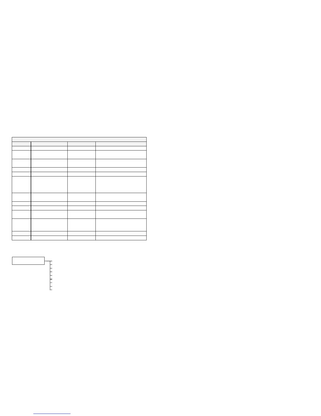
Control Wiring I/O
Terminal Name Purpose Comment
2 ANALOG INPUT 1 Process Setpoint 0V = 0%, 10V = 100%
3 ANALOG INPUT 2 Process Setpoint
Trim
0V = 0%, 10V = 100%
6 ANALOG OUTPUT 1 Ramp Output absolute speed demand
0V = 0%, 10V = 100%
12 DIGITAL INPUT 1 Run Forward 24V = run forward
13 DIGITAL INPUT 2 Run Reverse 24V = run reverse
14 DIGITAL INPUT 3 Not Stop 24V = RUN FWD and RUN
REV signals latched
0V = RUN FWD and RUN REV
signals not latched
15 DIGITAL INPUT 4 Remote Reverse 0V = remote forward
24V = remote reverse
16 DIGITAL INPUT 5 Jog 24V = jog
17 DIGITAL INPUT 6 PID Enable 24V = PID enable
18 DIGITAL INPUT 7 Remote Trip
Reset
24V = reset trips
19 DIGITAL INPUT 8 External Trip Non-configurable
0V = Trip
(connect to terminal 20)
21, 22 DIGITAL OUTPUT 1 Health 0V = tripped, i.e. not healthy
23, 24 DIGITAL OUTPUT 2 Running 0V = stopped, 24V = running
The Operator Menu for Macro 3
The default Operator Menu is shown below.
SPEED DEMAND
DRIVE FREQUENCY
MOTOR CURRENT
TORQUE FEEDBACK
DC LINK VOLTS
OPERATOR MENU
PROCESS SETPOINT
PROCESS FEEDBACK
PID ERROR
PID ENABLE

 Loading...


