Application Macros 5-16
690+ Series Frequency Inverter
Macro 6: “System” Drive
Provides for basic speed control with similar functionality to the 620 and 590+ Series Drives.
Control Wiring I/O
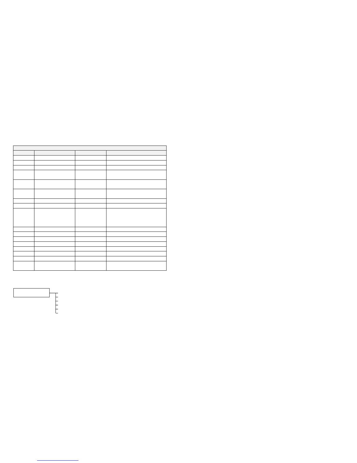
Terminal Name Purpose Comment
2 ANALOG INPUT 1 Speed Setpoint -10V = -100%, 10V = 100%
3 ANALOG INPUT 2 Speed Trim 1 -10V = -100%, 10V = 100%
4 ANALOG INPUT 3 Speed Trim 2 -10V = -100%, 10V = 100%
6 ANALOG OUTPUT 1 Ramp Output absolute speed demand
0V = 0%, 10V = 100%
7 ANALOG OUTPUT 2 Speed
Feedback
-10V = -100%, 10V = 100%
8 ANALOG OUTPUT 3 Torque
Feedback
-10V = -100%, 10V = 100%
12 DIGITAL INPUT 1 Run Forward 24V = Run forward
13 DIGITAL INPUT 2 Run Reverse 24V = Run reverse
14 DIGITAL INPUT 3 Not Stop 24V = RUN FWD and RUN REV
signals latched
0V = RUN FWD and RUN REV
signals not latched
15 DIGITAL INPUT 4 Reverse 24V = Reverse
16 DIGITAL INPUT 5 Jog 24V = Jog
17 DIGITAL INPUT 6 Drive Enable 24V = Drive Enable
18 DIGITAL INPUT 7 Fast Stop 0V = Fast Stop
19 DIGITAL INPUT 8 Coast Stop 0V = Coast Stop
21, 22 DIGITAL OUTPUT 1 Health 0V = Tripped, i.e. not healthy
23, 24 DIGITAL OUTPUT 2 At Zero Speed 0V = At Zero Speed Feedback
25, 26 DIGITAL OUTPUT 3 Switched On 0V = Open,
24V = Swtiched On
The Operator Menu for Macro 6
The default Operator Menu is shown below.
SPEED DEMAND
DRIVE FREQUENCY
MOTOR CURRENT
TORQUE FEEDBACK
OPERATOR MENU
SETPOINT (REMOTE)
DC LINK VOLTS

 Loading...


