Application Macros 5-19
690+ Series Frequency Inverter
Macro 7: Phase/Register
This macro is to be used in a slave drive set up for phase/register control. The slave will
get the line speed setpoint from the master drive via the system port (serial port using the
5703 setpoint repeater). This provides the highest accuracy and least lag. If this is not
possible, the speed demand should be derived from the master encoder using the
Encoder Speed function block, or over the network.
Note: Register control is enabled by setting REGISTER::RESET = FALSE
If Auto-gearing is enabled, then it is important that
PHASE CONFIGURE::SCALE A = PHASE CONFIGURE::SCALE B
Control Wiring I/O
Terminal Name Purpose Comment
6 ANALOG OUTPUT 1 Ramp Output absolute speed demand
0V = 0%, 10V = 100%
7 ANALOG OUTPUT 2 Speed Feedback -10V = -100%, 10V = 100%
8 ANALOG OUTPUT 3 Torque
Feedback
-10V = -100%, 10V = 100%
12 DIGITAL INPUT 1 Run Forward 24V = Run forward
13 DIGITAL INPUT 2 Run Reverse 24V = Run reverse
14 DIGITAL INPUT 3 Not Stop 24V = RUN FWD and RUN
REV signals latched
0V = RUN FWD and RUN REV
signals not latched
15 DIGITAL INPUT 4 Reverse 24V = Reverse
16 DIGITAL INPUT 5 Jog 24V = Jog
17 DIGITAL INPUT 6 Drive Enable 24V = Drive Enable
18 DIGITAL INPUT 7 Fast Stop 0V = Fast Stop
21, 22 DIGITAL OUTPUT 1 Health 0V = Tripped, i.e. not healthy
23, 24 DIGITAL OUTPUT 2 At Zero Speed 0V = At Zero Speed Feedback
25, 26 DIGITAL OUTPUT 3 Switched On 0V = Open,
24V = Swtiched On
System Board
A2 DIGITAL INPUT 11 Inch Advance
A3 DIGITAL INPUT 12 Inch Retard
A4 DIGITAL INPUT 13 Reset
5703 P3 Master Line Speed Demand
The Operator Menu for Macro 7
The default Operator Menu is shown below.
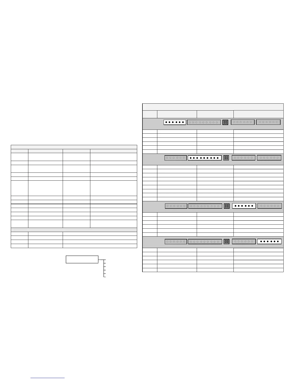
System Board Terminals (option)
Terminal
No.
Name Range Description
1 External 0V User-supplied 0V reference
2 DIGIO11 Configurable digital input/output
3 DIGIO12 Configurable digital input/output
4 DIGIO13 Configurable digital input/output
5 DIGIO14 Configurable digital input/output
6 DIGIO15 Configurable digital input/output
1 External 24V In 24V dc (±10%) 1A User-supplied power supply
2 Reference Encoder A Input
3 Reference Encoder /A Input
4 Reference Encoder B Input
5 Reference Encoder /B Input
6 Reference Encoder Z Input
7 Reference Encoder /Z Input
8 Encoder Supply Out 5V, 12V, 18V, 24V User selectable (max load 500mA)
9 External 0V User-supplied 0V reference
1 Slave Encoder A Input
2 Slave Encoder /A Input
3 Slave Encoder B Input
4 Slave Encoder /B Input
5 Slave Encoder Z Input
6 Slave Encoder /Z Input
1 Repeat Encoder Output A Output
2 Repeat Encoder Output /A Output
3 Repeat Encoder Output B Output
4 Repeat Encoder Output /B Output
5 Repeat Encoder Output Z Output
6 Repeat Encoder Output /Z Output
123456Terminal A
123456789Terminal B
123456Terminal C
123456Terminal D
SPEED DEMAND
DRIVE FREQUENCY
MOTOR CURRENT
TORQUE FEEDBACK
OPERATOR MENU
SETPOINT (REMOTE)
DC LINK VOLTS

 Loading...


