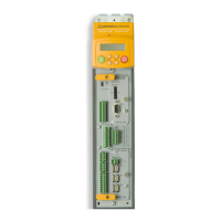
890SD Standalone Drive
Page 5-24 890CS Common Bus Supply - Frames B & D; 890CD Common Bus Drive and 890SD Standalone Drive - Frames B, C & D
8
9
10
11
B
C
D
1
2
3
4
5
6
7
E
ANALOG I/O
Name Range Description
01
0V 0V reference for analog I/O
02
AIN1
0-10V, ±10V
Analog Input 1 (default = diff I/P +)
03
AIN2
0-10V, ±10V
Analog Input 2 (default = diff I/P -)
04
AIN3
±10V, 0-10V,
0-20mA, 4-20mA
Analog Input 3 (default = remote setpoint I/P)
-10V = 100.00% reverse, +10V = 100.00% forward
(% maximum speed)
05
AIN4
±10V, 0-10V,
0-20mA, 4-20mA
Analog Input 4 (default = speed trim I/P)
06
AOUT1
±10V
(10V = 100% speed)
Analog Output 1 (default = speed feedback O/P)
07
AOUT2
±10V
(10V = 200% torque)
Analog Output 2 (default = torque feedback O/P)
08
+10V REF +10V (output) 10V reference for analog i/o. Load 10mA maximum
X12
09
–10V REF -10V (output) 10V reference for analog i/o. Load 10mA maximum
Note AIN1 and AIN2 are fitted with a link to ensure no noise pick-up when not in use. These terminals can be
used as a differential
±
10V input (which we call AIN5), but AIN1 and AIN2 must remain within
±
10V
relative to 0V. AIN5 has a direct input into the Speed Loop providing a fast speed or torque demand for
servos.
All analog inputs/outputs are configurable using the DSE 890 (Drive System Explorer) Configuration Tool
supplied on disk. The table above shows the factory defaults. These analog connections require ±10V DC
which is supplied at terminal X12/08 and X12/09 respectively. For further information refer to the DSE 890
Configuration Tool.

 Loading...