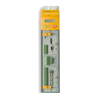
Keypad Menus
890CS Common Bus Supply - Frames B & D; 890CD Common Bus Drive and 890SD Standalone Drive - Frames B, C & D Page 9-7
8
9
10
11
B
C
D
1
2
3
4
5
6
7
E
The OPERATOR Menu
OPERATOR MENU
890CD Common Bus Drive & 890SD Standalone Drive
6511 Display 6901 Display
SETPOINT (xxxxxx)
Range: —.xx %
(Fixed as PREF 101.10) Indicates target speed. This will be equal to either:
LOCAL SETPOINT, REMOTE SETPOINT, JOG SETPOINT,
COMMS SETPOINT or FIREWIRE SETPOINT.
(Refer to the REFERENCE or REFERENCE JOG
function blocks)
SPEED DEMAND
Range: —.xx %
(Default: PREF 101.16) Indicates actual speed demand. This is the input to the Drive.
(Refer to the REFERENCE function block)
DRIVE FREQUENCY
Range: —.xx Hz
(Default: PREF 73.04) The Drive output frequency.
(Refer to the REFERENCE function block)
MOTOR CURRENT A
Range: —.xx A
(Default: PREF 70.13) This diagnostic contains the level of rms line current being drawn from the Drive.
(Refer to the REFERENCE function block)
TORQUE FEEDBACK
Range: —.xx %
(Default: PREF 70.10) Shows the estimated motor torque, as a percentage of rated motor torque.
(Refer to the REFERENCE function block)
DC LINK VOLTS
Range: —. V
(Default: PREF 70.02) This shows the voltage on the dc link capacitors.
(Refer to the REFERENCE function block)

 Loading...