Operating the Drive
Page 7-2 890CS Common Bus Supply - Frames B & D; 890CD Common Bus Drive and 890SD Standalone Drive - Frames B, C & D
8
9
10
11
B
C
D
1
2
3
4
5
6
7
E
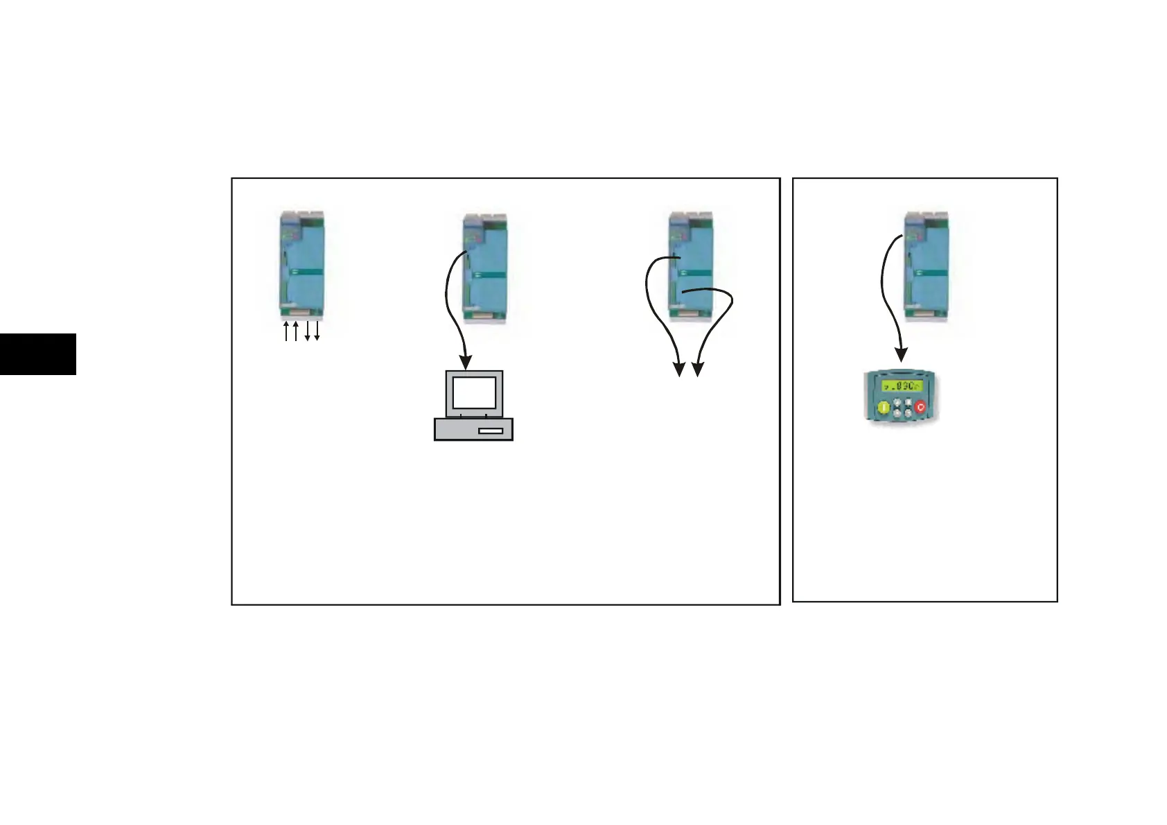
Control Philosophy
There are four ways to control the drive using Remote and Local control:
analog
and digital
inputs and
outputs
PC running
DSE 890
Configuration Tool
Option Card A
REMOTE
CONTROL
890 drive using
LOCAL
CONTROL
and Option Card B
to fieldbus
and
Comms link
Keypad
890CD Frame D illustrated
890 drive using 890 drive using 890 drive using
Figure 7.1 Remote and Local Control Modes

 Loading...


