890CS & 890CD Common Bus Units
Page
4-2
890CS Common Bus Supply - Frames B & D; 890CD Common Bus Drive and 890SD Standalone Drive - Frames B, C & D
8
9
10
11
A
B
C
D
1
2
3
4
5
6
7
E
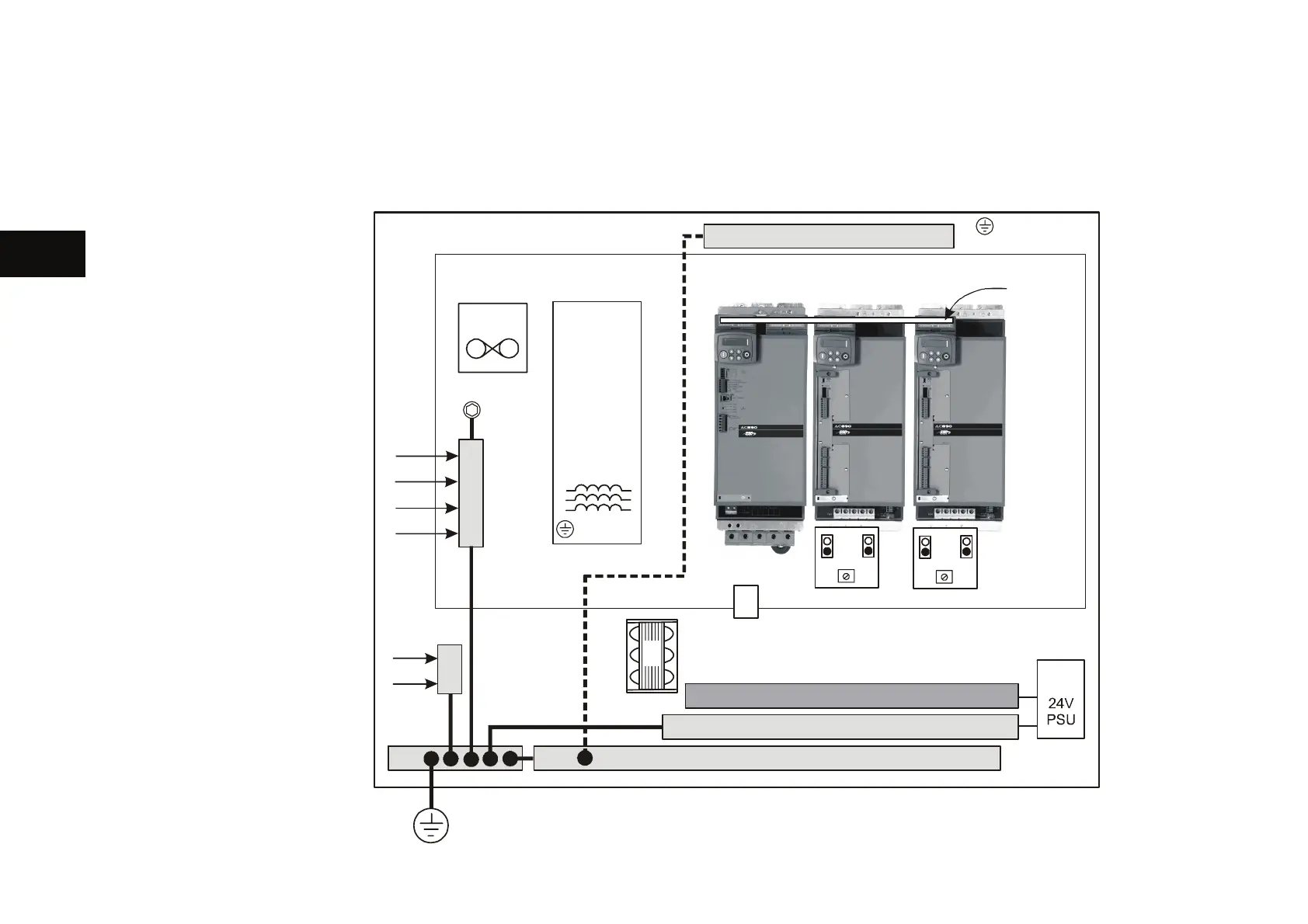
Step 1: Mechanical Installation
Install the 890 units and associated equipment into the cubicle. The diagram shows a typical layout using
Star Point earthing for EMC compliance. Refer to Appendix C for further information.
KEY
A
Analog Clean
Earth
B
Back plate
C
Cubicle
E
Dirty Earth
F
Filter (optional)
G
Star Point
Earth/Ground
M
Metal Work Earth
P
Fuse or
circuit breaker
R
AC Line Reactor
(mandatory)
S
Signal/Control
Screen Earth
T
24V Power Supply
V
3 Phase
AC Contactor
890CD 890CD
PF
C
G
890CS
R
E
A
DC
M
S
B
*
PE2
24V
+
-
E
T
V

 Loading...


