Programming
Page
D-2
890CS Common Bus Supply - Frames B & D; 890CD Common Bus Drive and 890SD Standalone Drive - Frames B, C & D
8
9
10
11
A
B
C
D
1
2
3
4
5
6
7
E
Programming with Block Diagrams
You can program the drive to your specific application. This programming simply involves changing
parameter values. For instance, parameter
S
1 selects the main method of motor control used by the drive:
Volts/Hz or Sensorless Vector.
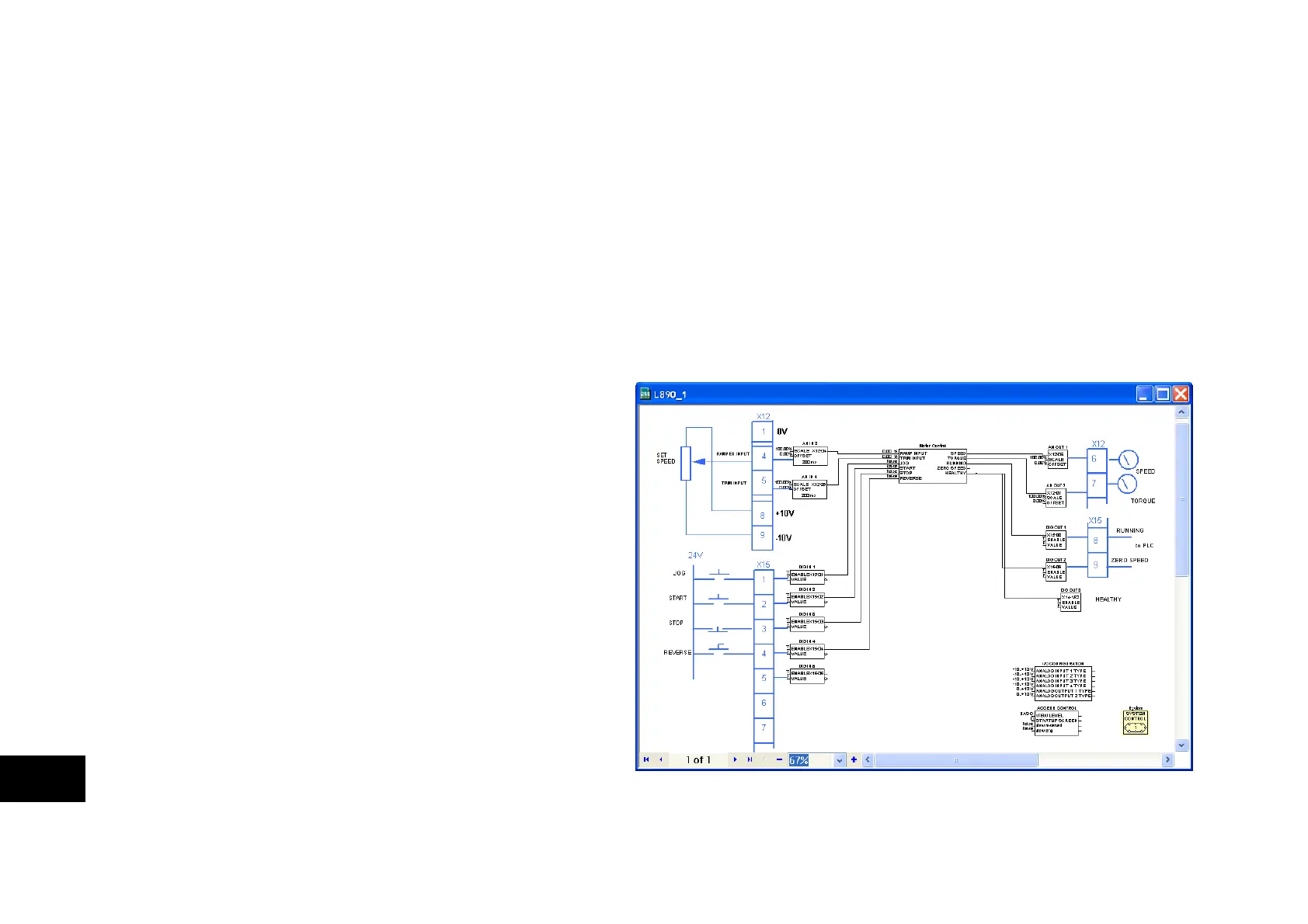
Block diagram programming provides a visual method of planning the software to suit your application.
The blocks described here are those blocks used by the Shipping Configuration(s) in the DSE 890
Configuration Tool. A typical block diagram as seen in the DSE 890 Configuration Tool is shown below.
The processes performed by the shipping configuration are represented as a block diagram, consisting of
function blocks and links:
• Each function block contains
the parameters required for
setting-up a particular
processing feature. Sometimes
more than one instance of a
function block is provided for a
feature, i.e. for multiple digital
inputs.
• Software links are used to
connect the function blocks.
Each link transfers the value of
an output parameter to an input
parameter of another (or the
same) function block.
Each individual block is a processing feature, i.e. it takes the input parameter, processes the information,
and makes the result available as one or more output parameters.

 Loading...


