EasyManuals Logo

Parker ac890 Reference Manual

Parker ac890
640 pages
To Next Page IconTo Next Page
To Previous Page IconTo Previous Page
Page #17 background imageLoading...
Page #17 background image
Product Overview
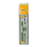
890CS Common Bus Supply - Frames B & D; 890CD Common Bus Drive and 890SD Standalone Drive - Frames B, C & D Page 3-5
8
9
10
11
A
B
C
D
1
2
3
4
5
6
7
E
Functional Diagrams
Figure 3.1 Functional Block Diagram of 890CS Common Bus Supply & 890CD Common Bus Drive
L1
L2
L3
Half
Controlled
Rectifier
Switch
DBR+
DBR-
BUSBARS
+24V OUT
DIGIN 1
ENABLE
AOUT MODE
AOUT
0V OUT
X02
890CS Common Bus Supply
PROCESSOR
AUXILIARY
SUPPLY
X01
+24V
0V
+24V
0V
VOLTAGE SELECTOR
DC Link Supply
+
-
M1 M2 M3
UVW
Filter
890CD Common Bus Drive
BUSBARS
+
-
PROGRAMMING
PORT
mini-USB
X
13
+24V
0V
+24V
0V
DIN1
DIN2
DIN3
DIN4
DIN5
DIN6
DIN7
DIN8/DOUT1
DIN9/DOUT2
X15
DIGITAL I/O
INTERFACE
KEYPAD
INTERFACE
KEYPAD
HMI REMOTE
PROGRAMMING
PORT
RS232
0V
AIN1
AIN2
AIN3
AIN4
A
OUT1
A
OUT2
+10V
-10V
ANALOG I/O
X12
X
11
PUMR A POS
PUMR A NEG
PUMR B POS
PUMR B NEG
CONNECTOR
(for future use)
SUPPLY
X
14
A
24V
B
0V
HMI REMOTE
PROGRAMMING
PORT
RS232
X04
PRE-TRIP WARNING
HEALTH
X03
S1
X10
OPTION F
SPEED
INTERFACE
FEEDBACK
OPTION A
OPTION B
FIELDBUS
INTERFACE
COMMS
FIELDBUS
INTERFACE
COMMS
MECHANICAL
BRAKE THERMISTOR
DC+
DC-

Table of Contents

Other manuals for Parker ac890

Questions and Answers:

Question and Answer IconNeed help?

Do you have a question about the Parker ac890 and is the answer not in the manual?

Parker ac890 Specifications

General IconGeneral
BrandParker
Modelac890
CategoryDC Drives
LanguageEnglish

Related product manuals