890CS & 890CD Common Bus Units
890CS Common Bus Supply - Frames B & D; 890CD Common Bus Drive and 890SD Standalone Drive - Frames B, C & D Page
4-23
8
9
10
11
A
B
C
D
1
2
3
4
5
6
7
E
8
9
1
2
3
4
5
6
E
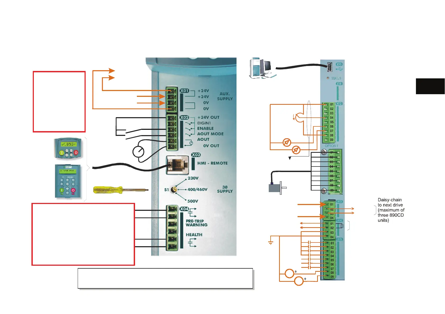
Control Connection Diagram
You cannot change between Local & Remote modes
when ENABLE at X02 is at 24V
Enabled
.
24V DC
890CS COMMON BUS SUPPLY
24V DC
Programming Port
USB
Speed
Potentiometer
Encoder
HEALTH
ZS
DR
To c o nt r o l b r a c k e t
24V DC
890CD COMMON BUS DRIVE
0V
AIN1
AIN2
AIN1
AIN4 - SPEED TRIM
AIN3 - REMOTE SETPOINT
AOUT 2 - TORQUE FEEDBACK
AOUT1 - SPEED FEEDBACK
-10V
+10V
SHIELD
-
+
Z
Z/
B
B/
A
A/
24V DC
0V
24V
0V
24V DC
0V
DOUT3A
DOUT3B
DIN1 - JOG
DIN3 - STOP
DIN2 - RUN
DIN5 - unassigned
DIN4 - REVERSE
DIN7 - unassigned
DIN6 - unassigned
DINOUT2 - ZERO SPEED
DINOUT1 - RUNNING
Terminals
X04/01 & X04/02, X04/05 & X04/06
If the supply to these volt-free relays is
>25Vac rms or >60V dc,
you must provide an appropriate fusing
system of 10A for the supply to these
digital outputs to comply with UL
Earthing Requirements.
Terminal X02/03
ENABLE
is intended as an
aid to functional
sequencing only
and must NOT be
used as the main
system disable.

 Loading...


