890SD Standalone Drive
890CS Common Bus Supply - Frames B & D; 890CD Common Bus Drive and 890SD Standalone Drive - Frames B, C & D Page 5-27
8
9
10
11
B
C
D
1
2
3
4
5
6
7
E
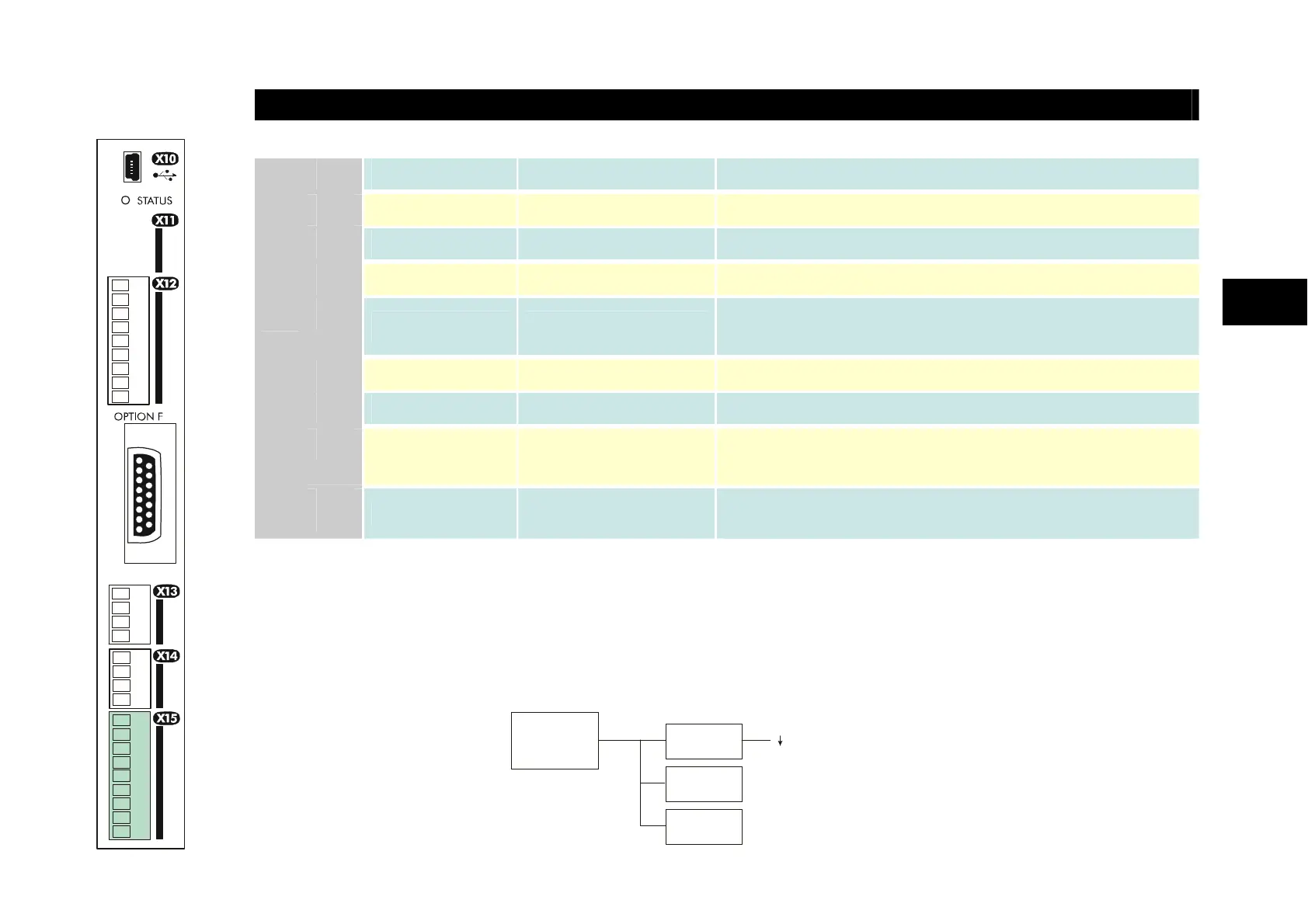
DIGITAL I/O
Name Range Description
01
DIN1 0-24V DC Digital Input 1 (default = JOG)
02
DIN2 0-24V DC Digital Input 2 - (default = RUN)
03
DIN3 0-24V DC Digital Input 3 - (default = STOP)
04
DIN4 0-24V DC Digital Input 4 - (default = REVERSE)
05
DIN5 0-24V DC
Digital Input 5 - (default = unassigned). Refer to I/O
TRIPS::EXT TRIP MODE for special function.
06
DIN6 0-24V DC Digital Input 6 - (default = unassigned)
07
DIN7 0-24V DC Digital Input 7 - (default = unassigned)
08
DIN8/DOUT1 0-24V DC
Digital Input/output 1 -
(default = digital output: RUNNING)
X15
09
DIN9/DOUT2 0-24V DC
Digital Input/output 2 -
(default = digital output: ZERO SPEED)
All digital inputs/outputs are configurable using the DSE 890 (Drive System Explorer) Configuration Tool
supplied on disk. The table shows the factory defaults. The digital inputs require 24V DC which is supplied
at terminal X14/03. For further information refer to the DSE 890 Configuration Tool.
Note The maximum permissible sum of currents from X14/03, X15/08, X15/09 is 150mA. The load on X15/08
& X15/09 connects from these pins to X14/04 (0V). An Alert message will be displayed if exceeded.
SUPPLY
150mA
X14/03
X15/08
X15/09
X15/01
X15/07
(7mA each)

 Loading...


