Programming
Page
D-114
890CS Common Bus Supply - Frames B & D; 890CD Common Bus Drive and 890SD Standalone Drive - Frames B, C & D
8
9
10
A
B
C
D
E
1
2
3
4
5
6
7
Parameter Descriptions
MODE
PREF: 121.16 Default: 0 Range: See below
This diagnostic shows the operating mode of the position loop. (Range: Enumerated – 0: DISABLED, 1: ENABLED, , 2:
UNSYNCHRONISED, 3: SYNCHRONISED , 4: ABSOLUTE,.)
Enumerated Value : Mode
0 : DISABLED The position loop is disabled.
1 : ENABLED The position loop is enabled, but not operating
2 : UNSYNCHRONISED The position loop is operating, but this drive has not been
synchronised to the master by a Move To Master operation
3 : SYNCHRONISED The position loop is operating, and the drive has been
synchronised to the master, by a Move To Master operation
4 : ABSOLUTE The position loop is operating with demands from the Phase
Move Abs block
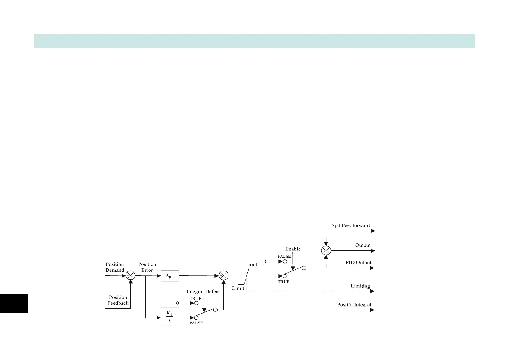
Functional Description
The position error (position demand – position feedback) is calculated and processed by a proportional + integral (PI)
controller. The output of the PI controller is a speed demand, which is passed directly to the speed loop block. (speed loop
Speed Demand = position loop Output. Note that speed loop Phase Input = 0).

 Loading...


