890CS & 890CD Common Bus Units
Page
4-28
890CS Common Bus Supply - Frames B & D; 890CD Common Bus Drive and 890SD Standalone Drive - Frames B, C & D
8
9
10
11
A
B
C
D
1
2
3
4
5
6
7
E
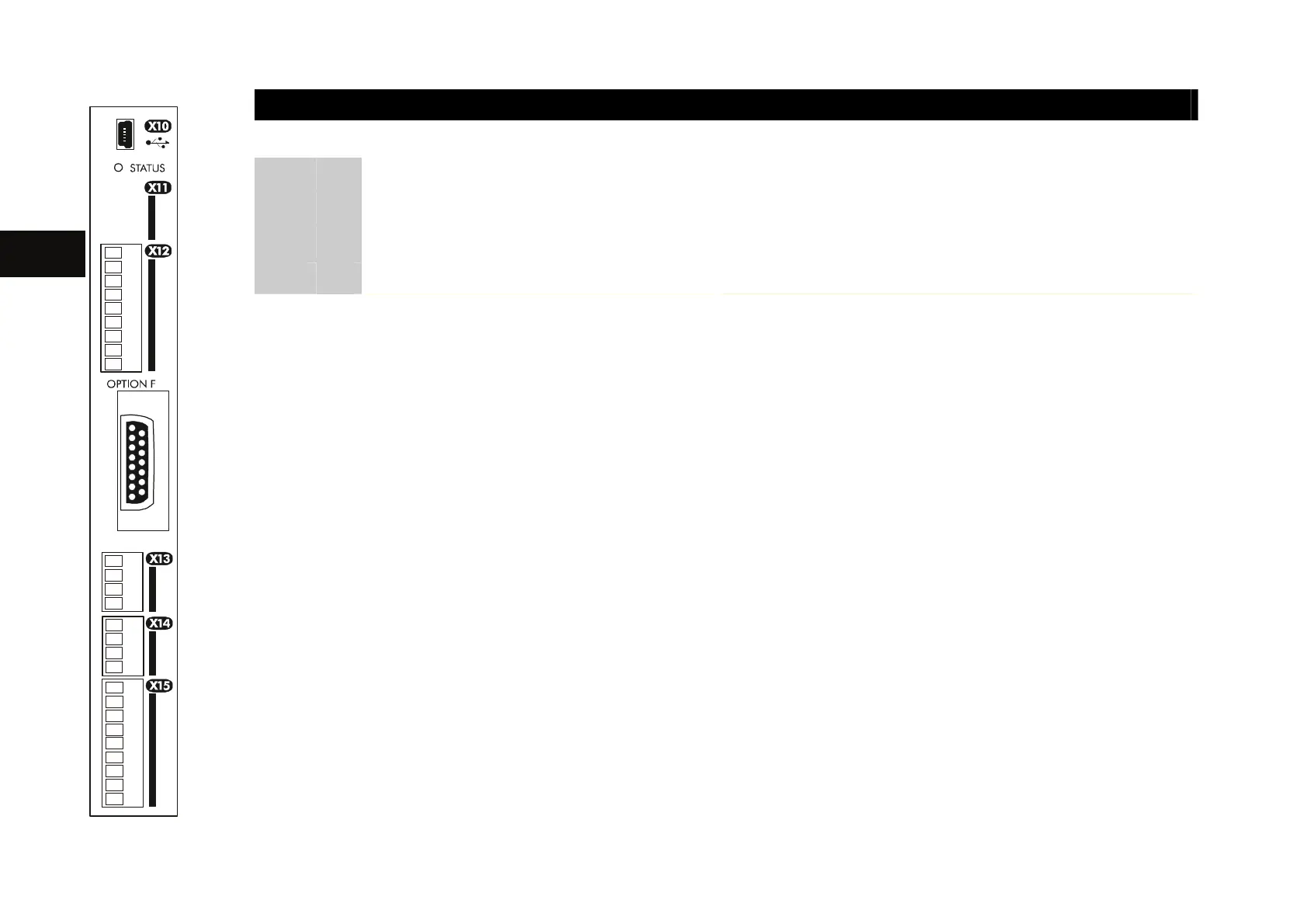
FUTURE USE
Name Range Description
01
PUMR A+ 0-24V 24V DC enables drive operation
02
PUMR A- 0V
03
PUMR B+ 0-24V 24V DC enables drive operation
X11
04
PUMR B- 0V
Note Both inputs (PUMR A: terminals 01 & 02 and PUMR B: 03 & 04) must be at 24V to enable the drive.
PUMR is designed to prevent a motor from starting, for example: during machine maintenance.
(You could connect the operation of the inputs PUMR A and PUMR B to the placement of motor
guards/covers).
If the voltage on either pair is removed while a drive is running, the motor will coast to stop,
however, safety comes from redundancy (both pairs).
WARNING
Individually, PUMR A or PUMR B is not guaranteed to prevent a motor from starting.
PUMR is not designed as a safe means of stopping a spinning motor.
PUMR ensures mechanical safety; but not electrical safety: hazardous voltages remain in the
drive and can appear at the motor, but the voltage patterns needed to turn a motor will not be
present.
Reporting is via the Health relay (X14). Healthy = both PUMR inputs energised, the drive can
start, possibly without warning or user command. This reporting mechanism must not be used
as part of a safety system. It is intended as an indication only; its function is not guaranteed in
any way.
Refer to ? for a drawing of the PUMR internal workings.
totally
isolated
totally
isolated
Terminal X11 is for future use.

 Loading...


