17C ENGINE TIMING
To check the timing mark of the fuel
injection pump17C-04
Special tools:
Universal timing tool, MS.67B
Gear adaptor for use with MS.67B, PD.67-3
1Remove the fuel injection pump, operation
20D-06.
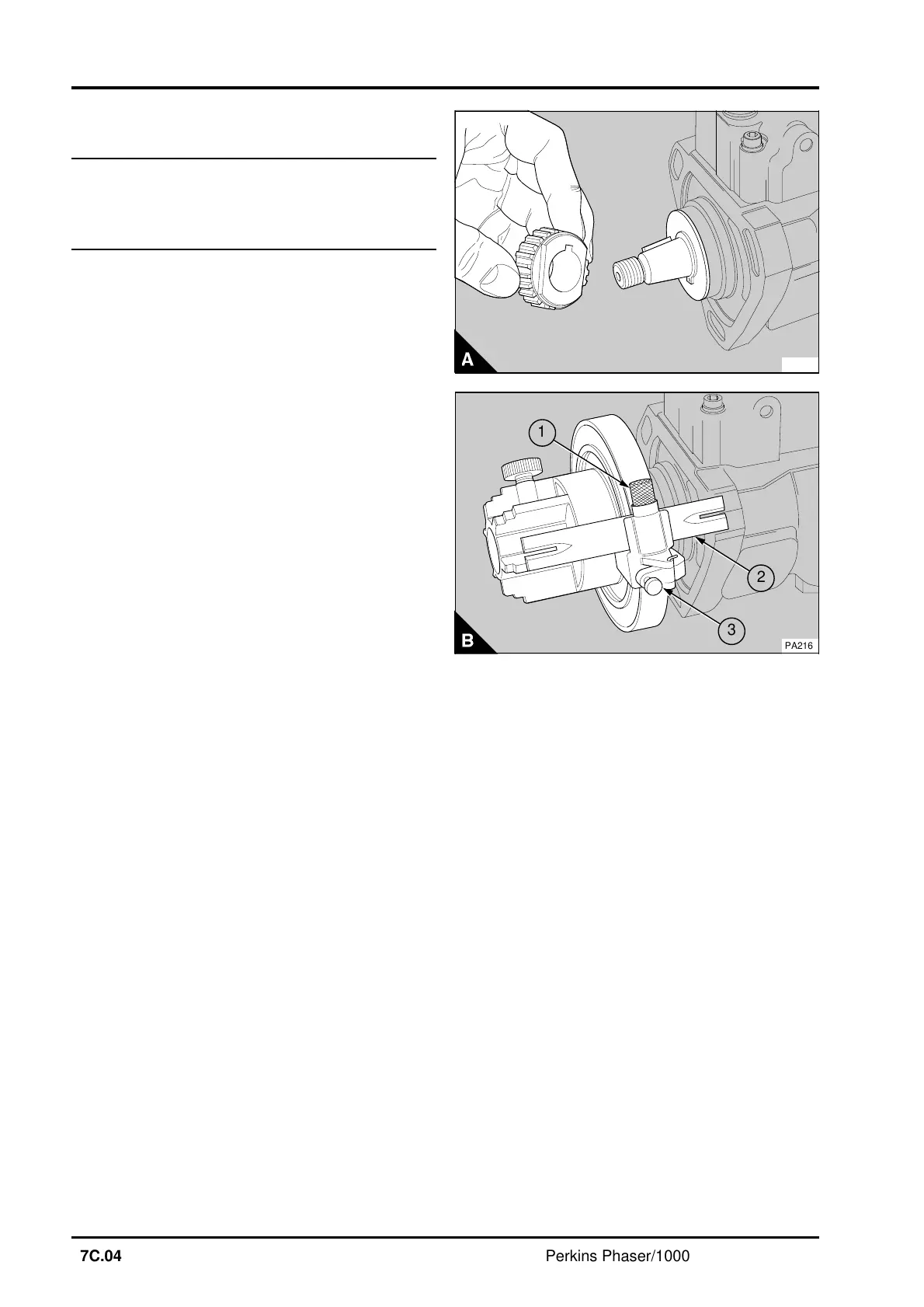
2 Fit the adaptor PD.67-3 (A) to the drive shaft of
the fuel pump and fasten it with the nut of the fuel
pump gear.
3 Remove the banjo bolt from number 1 high-
pressure outlet - outlet "W" for four cylinder
engines, outlet "Y" for six cylinder engines - and fit
a banjo bolt which does not contain a pressure
valve.
4 Connect number 1 outlet to an atomiser tester.
Operate the hand pump until a pressure of 30 atm
(440 lbf in
2
) 31 kgf/cm
2
is indicated on the gauge.
5 Loosen the screw (B3) on the timing tool
MS.67B and set the timing tool to the correct angle,
see data and dimensions. Tighten the screw.
6 Fit the timing tool to the adaptor on the fuel
pump drive shaft. Rotate the drive shaft of the fuel
pump by hand in the normal direction of rotation -
see arrow on pump data plate - until the fuel
pressure prevents movement. In this position, the
fuel pump is set at the start of injection from
number 1 outlet.
7 Loosen the screw (B1). Slide the pointer (B2)
forward until it is over the centre of the pump flange
and check that the mark on the flange is in the
centre of the slot in the pointer.
8 If the mark is not correct, remove the timing tool
and eliminate the mark. Fit the timing tool and
ensure that the fuel pump is at the start of injection
for number 1 cylinder. Loosen the screw (B1). Slide
the pointer forward to the complete width of the
flange and tighten the screw. Make a new mark on
the flange of the pump through the slot in the
pointer.
9 Remove the timing tool and the adaptor.
10 Disconnect the atomiser tester and fit the
original banjo bolt to number 1 high-pressure outlet.
11Fit the fuel injection pump, operation 20C-06.
12Eliminate air from the fuel system, operation
20C-08.
PA215
1
a
a
3
a
a
2
PA216
17C.04 Perkins Phaser/1000 Series, April 1995