AXC F 1050
36 / 140
PHOENIX CONTACT 107709_en_00
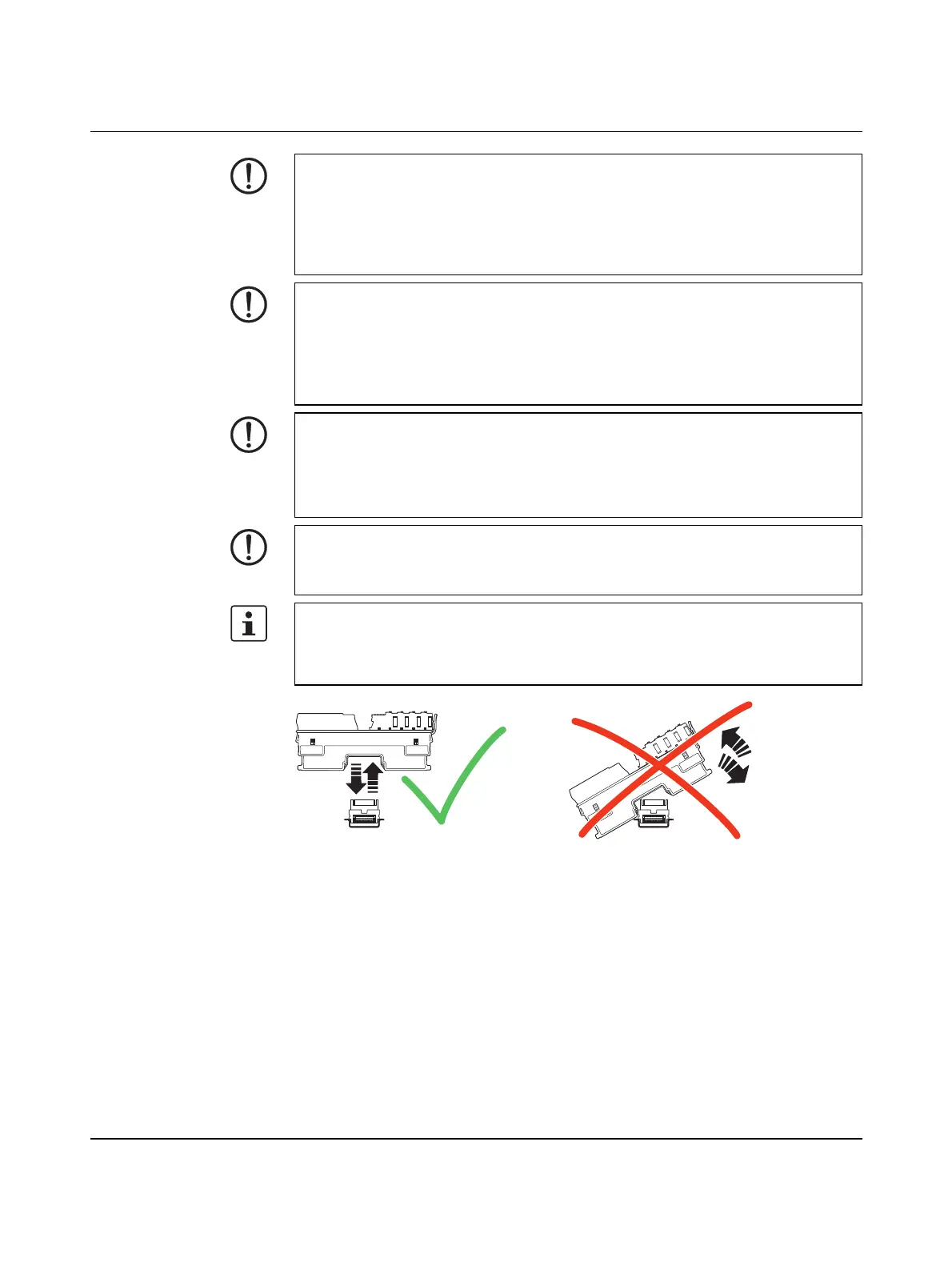
Figure 4-1 Placing the module vertically
NOTE: Device failure due to operation above the permitted specifications for vi-
brations and shock
If the device is subjected to vibrations and shock levels above the permitted specifications
during operation, this may lead to malfunctions or even device failure.
• Ensure that the permitted specifications for vibrations and shocks are adhered to
when operating the device, see Section 12.1
NOTE: Property damage due to impermissible stress
The IP20 degree of protection (IEC 60529/EN 60529) requires that the device be used in
a clean and dry environment. If you use the device in an environment that is outside of the
specified limits, this may cause damage to the device.
• Do not subject the device to mechanical or thermal stress that exceeds the specified
thresholds.
NOTE: Component breakage and/or short circuit
Inserting the device connectors (RJ45 connectors or USB connectors) into sockets for
which they were not designed can lead to components being broken and/or device short
circuit.
• Plug each connector only into the socket on the device intended for that connector.
NOTE: Damage to the contacts when tilting
Tilting the modules can damage the contacts.
• Place the modules onto the DIN rail vertically (see Figure 4-1).
The controller is automatically grounded (FE) when it is snapped onto a grounded
DIN rail.
There are two FE springs on the back of the controller that make contact with the DIN rail
when the controller is placed on the DIN rail.
 Loading...


