Attach an innermost sidewall panel 1 to each side
attaching flange using seven TEK self-tapping screws.
NOTE: Flanges face inward.
Description Part Number
Left Side Panel #1 13205080 / 13305080
Right Side Panel #1 13205081 / 13305081
TEK Screws 13404
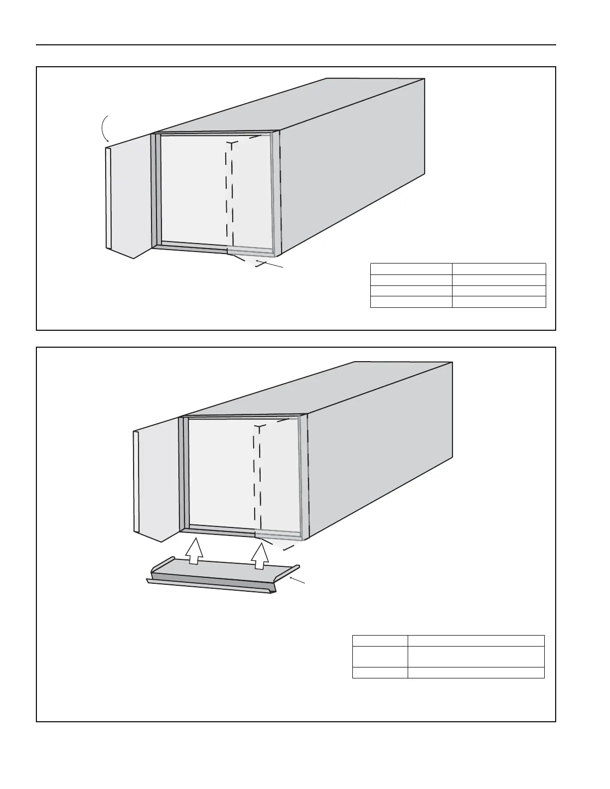
For Model 2020: Attach the bottom panel to the bottom
mounting flange with seven TEK self-tapping screws. Attach
to each side panel with two TEK self-tapping screws.
For Model 2030: Attach bottom panel to the bottom mounting
flange with nine TEK self-tapping screws. Attach to each side
panel with two TEK self-tapping screws.
NOTE: Ensure that the side tabs of the bottom panel are to
the inside of the side panels.
Description Part Number
Bottom Rail
13205072 / 13305072 /
13205095 / 13305100
TEK Screws 13404