Because RFL™ and Hubbell® have a policy of continuous product improvement, we reserve the right to change designs and specifications without notice.
The timing mode selected by the user is called the primary timing mode. IMUX 2000 multiplexers
may also operate in a fallback timing mode. Specifically, when configured for External, Loop, or
Through timing, if the primary timing source becomes unavailable, an IMUX 2000 multiplexer
performs an automatic fallback to an alternate source of timing. For example, the internal oscillator
may be selected as the fallback source.
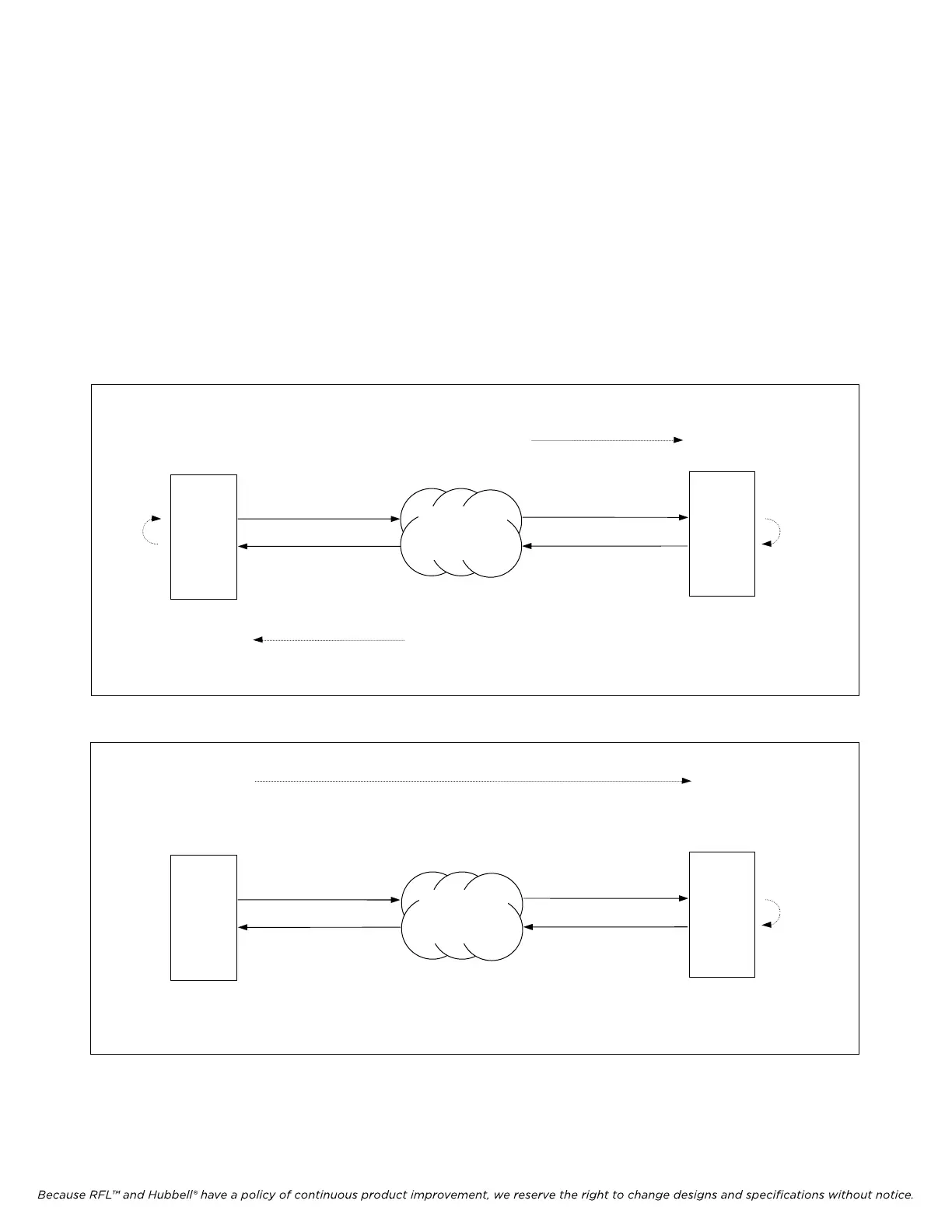
Appropriate uses of each of the four E1 transmitter timing modes are illustrated in Figures 5-7 through
5-11. Note that in IMUX 2000 systems synchronized to the digital network, both terminal multiplexers
will normally be loop timed (Figures 5-7 and 5-9). In IMUX 2000 systems timed from one end and not
synchronized to the carrier's network, one terminal multiplexer will be internally (or externally) timed
while the other is loop timed (Figures 5-8 and 5-10). Figure 5-11 shows how an IMUX 2000 system
can use an external timing source.
IMUX 2000E1 RFL Electronics Inc.
Figure 5-7. Point-to-point system synchronized to the network which forces timing onto E1 signal
Figure 5-8. Point-to-point system internally timed from one end (not synchronized to the network)
IMUX 2000
IMUX 2000
IMUX 2000
LOOP
TIMED
TIMED
LOOP
TIMED
LOOP
TIMED
TIMING
TIMING
IMUX 2000
INTERNALLY
TIMING
E1 CIRCUIT
E1 CIRCUIT
E1 CIRCUIT
E1 CIRCUIT
NETWORK
(ELECTRICAL
OR FIBER)
NETWORK
(ELECTRICAL
OR FIBER)
January 1, 2008 5-11 (973) 334-3100
 Loading...
