Because RFL™ and Hubbell® have a policy of continuous product improvement, we reserve the right to change designs and specifications without notice.
2.3.5 POWER SUPPLY MODULES
IMUX 2000 multiplexers can be configured with five different power supplies that can operate with the
following input voltages: 120 Vac, 220 Vac, 24 Vdc, 48 to 125 Vdc, or 250 Vdc. (The specifications listed in
Section 11 of this manual provide more information on power supply input voltage ranges, input fuse
requirements, and output power ratings.) The Main Shelf can contain one or two power supplies with the same
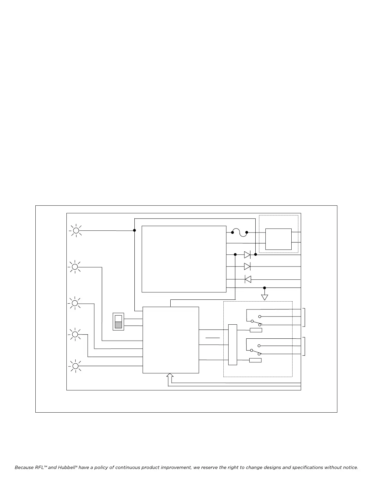
capacity. A functional block diagram of the IMUX 2000 Power Supply and the Power Supply Alarm I/O module
appears in Figure 2-16.
The first power supply inserts into the "P.S. MAIN" slot. The second optional power supply inserts into the
"P.S. REDUNDANT" slot. As configured at the factory, all Main Shelves can be powered by one power supply
module. The second power module, if installed, provides power supply redundancy; if the main power supply
fails, the redundant supply automatically comes on-line, with no loss of transmission.
If you are adding modules to an existing system equipped with dual power supplies, always verify that total
power consumption does not exceed the capacity of a single supply. This will insure power supply redundancy.
(See Section 3 for more information.)
Channel modules on the optional Repeater Shelf receive power from the Main Shelf supply through the
Repeater Shelf Power Cable. However, if the Main Shelf supply does not have sufficient excess capacity, the
Repeater Shelf can contain its own power supply. Like the Main Shelf, the Repeater Shelf can contain a second
supply with equal capacity for power supply redundancy.
FAIL
ALERT
SUPPLY
FAIL
NORMAL
POWER
AC or DC
INPUT
+5 VOLTS
+15 VOLTS
-15 VOLTS
COMMON
ALERT
CONTACTS
FAIL
CONTACTS
STATUS SIGNALS
FROM
COMMON
MODULE
EMI AND
SWC
FILTER
POWER SUPPLY
ALARM
CONTROL
CIRCUIT
PART OF PS ALARM
I/O MODULE
ACO
SWITCH
P
WER FAIL
EN
E
RELAY
LOGIC
COM
N.C.
N.O.
COM
N.O.
N.C.
FAIL
PSTAT0
ALM_DIS
FUSE
PART OF PS
ALARM I/O MODULE
NOTE: THE RELAY IS ENERGIZED UNDER NORMAL OPERATING CONDITIONS AND DE-ENERGIZED DURING ALARM
CONDITIONS. THE RELAY IS SHOWN IN THE NON-ALARM STATE.
Figure 2-16. Functional diagram, IMUX 2000 Power Supply and Power Supply Alarm I/O module
IMUX 2000E1 RFL Electronics Inc.
April 1, 2007 2-26 (973) 334-3100