Because RFL™ and Hubbell® have a policy of continuous product improvement, we reserve the right to change designs and specifications without notice.
IMUX 2000E1 RFL Electronics Inc.
April 1, 2007 2-4 (973) 334-3100
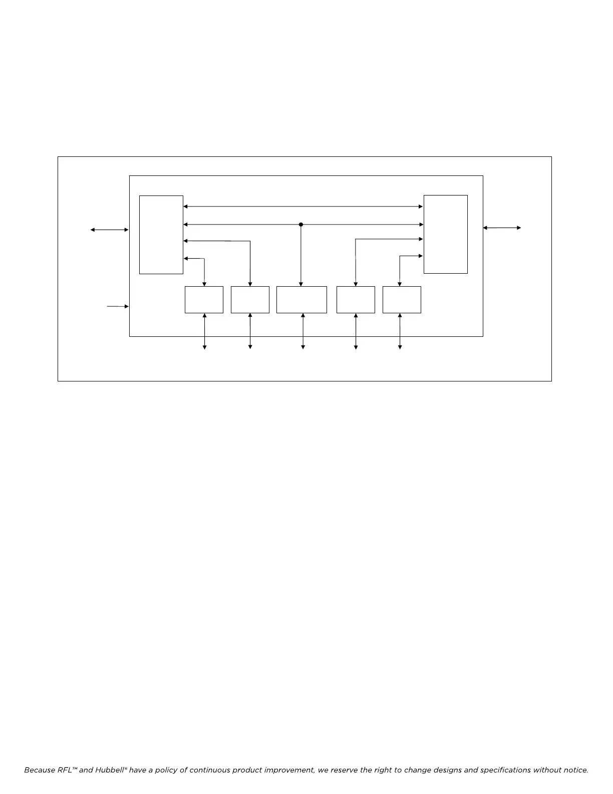
2.2.2 DROP/INSERT MULTIPLEXER
A drop/insert multiplexer is essentially a multiplexer configured as two back-to-back terminals, in
which some circuits terminate while others pass through. A drop/insert multiplexer can terminate
payload circuits from either of two different E1 circuits; that is, from either of two different locations.
(See Figure 2-3.)
CHANNEL
MODULES
E1 CIRCUIT
(ELECTRICAL OR
FIBER)
VOICE
MODULE
VOICE
MODULE
DATA
MODULE
DATA
MODULE
ORDERWIRE
MODULE
P A Y L O A D C I R C U I T S
COMMON
MODULE(S)
COMMON
MODULE(S)
E1 CIRCUIT
(ELECTRICAL OR
FIBER)
DROP/INSERT MULTIPLEXER
Figure 2-3. Drop/insert multiplexer (sample configuration)
2.2.3 POINT-TO-POINT SYSTEMS
The simplest type of IMUX 2000 system configuration is a point-to-point system. A point-to-point
system consists of two terminal multiplexers connected by a single E1 electrical or fiber optic circuit.
(See Figure 2-4.) As the figure illustrates, the same payload circuits will appear at both ends of a point-
to-point system. Most payload types (such as voice and full-duplex data circuits) are bi-directional, and
will have both an input and an output at each terminal multiplexer.
2.2.4 DROP/INSERT SYSTEMS
The addition of one or more drop/insert multiplexers converts a simple point-to-point system into a
drop/insert system. (See Figure 2-5.) Data, voice, and orderwire (multiple drop voice) circuits can be
established between any two locations in a E1 drop/insert system. As shown in Figure 2-5, a three-
location system can provide circuits between Locations 1 and 2, Locations 2 and 3, and Locations 1
and 3. The only limiting factor is the capacity of the E1 circuit between any two adjacent locations,
which is 24 time slots. Drop/insert systems are not limited to a single drop/insert multiplexer, and may
contain more than three locations.