Because RFL™ and Hubbell® have a policy of continuous product improvement, we reserve the right to change designs and specifications without notice.
6.5.3 GETTING STARTED
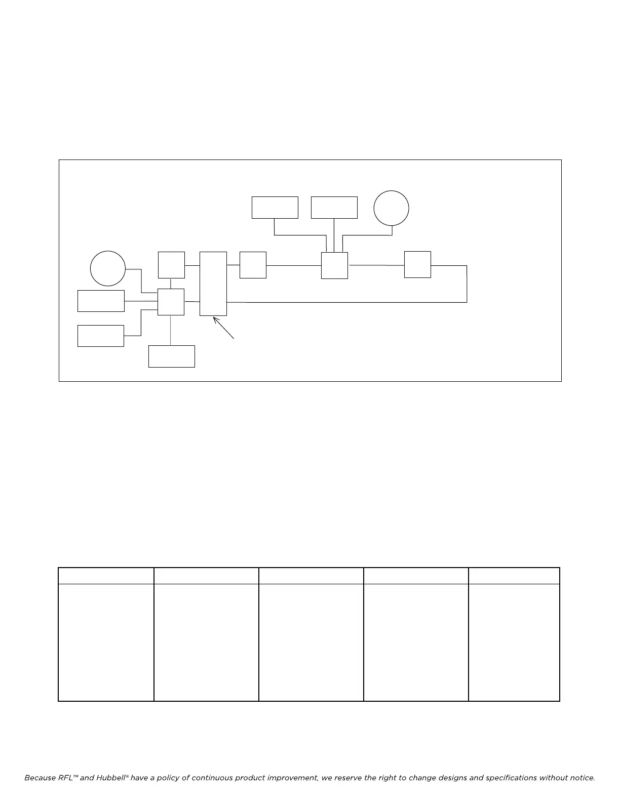
Figure 6-9 shows a simplified drawing of the network that will be used for this example. Figure 6-10
shows a more detailed drawing of the network showing all IMUX 2000 components, modules, cards
and cables used in the network example.
Figure 6-9. Basic drawing of the network used in the example
The network used in this example has 5 nodes. Nodes 1 and 5 each have one terminal end multiplexer
head and tailed at one location to form a ring using a common DACS. All other nodes around the ring
have Drop and Insert multiplexers, each utilizing a DACS. Data and voice circuits are established
between node 1 and node 3, which consist of one phone line, one RFL 9300 charge comparison system
data link, and one RFL 9745 teleprotection data link. Table 6-1. lists the modules and cards in each
node that must be configured into the network.
Table 6-1. List of modules and cards used in the example that must be configured into the network
Node 1 (Terminal) Node 2 (Drop/Insert) Node 3 (Drop/Insert) Node 4 (Drop/Insert) Node 5 (Terminal)
DACS-R
CM4-1 (main)
CM4-1 (standby)
VF5C
1
2
3
4
5
PHONE
9300
9745
9745
9300
PHONE
PC OR
LAPTOP
Common DACS
VF16B
DS562I
NCM
DACS-R
CM4-1 (main)
CM4-1 (standby)
IMUX 2000E1 RFL Electr
o
nics Inc.
CM4-2 (main)
CM4-2 (standby)
DACS-R
CM4-1 (main)
CM4-1 (standby)
CM4-2 (main)
CM4-2 (standby)
VF5C
VF16B
DS562I
NCM
DACS-R
CM4-1 (main)
CM4-1 (standby)
NCM
CM4-1 (main)
CM4-1 (standby)
February 28, 2006 6-14 (973) 334-3100
 Loading...
