Because RFL™ and Hubbell® have a policy of continuous product improvement, we reserve the right to change designs and specifications without notice.
Section 3. CM4 COMMON MODULE REDUNDANT PROTECTION MODE
3.1 REDUNDANT PROTECTION MODE
CM4 Common Modules may be utilized in 1x1-protection schemes. Each Common Module in an
IMUX shelf can be provided with a standby substitute, which will take over in the event of module
failure.
3.1.1 PHYSICAL CONFIGURATION.
Each Multiplexer Function (Terminal, Drop-and-Insert A, or Drop-and-Insert B) requires two CM4
common modules for protected operation, one inserted into the Main operating slot, and the other
inserted into the Standby slot. One redundant Module Adapter in the rear of the shelf is required for
each Main/Standby pair of Common Modules.
For example, a fully protected Drop-and-Insert shelf will utilize a total of four CM4s, two for DI-A
and two for DI-B, as well as one redundant Module Adapter (Electrical or Optical) for DI-A and one
for DI-B.
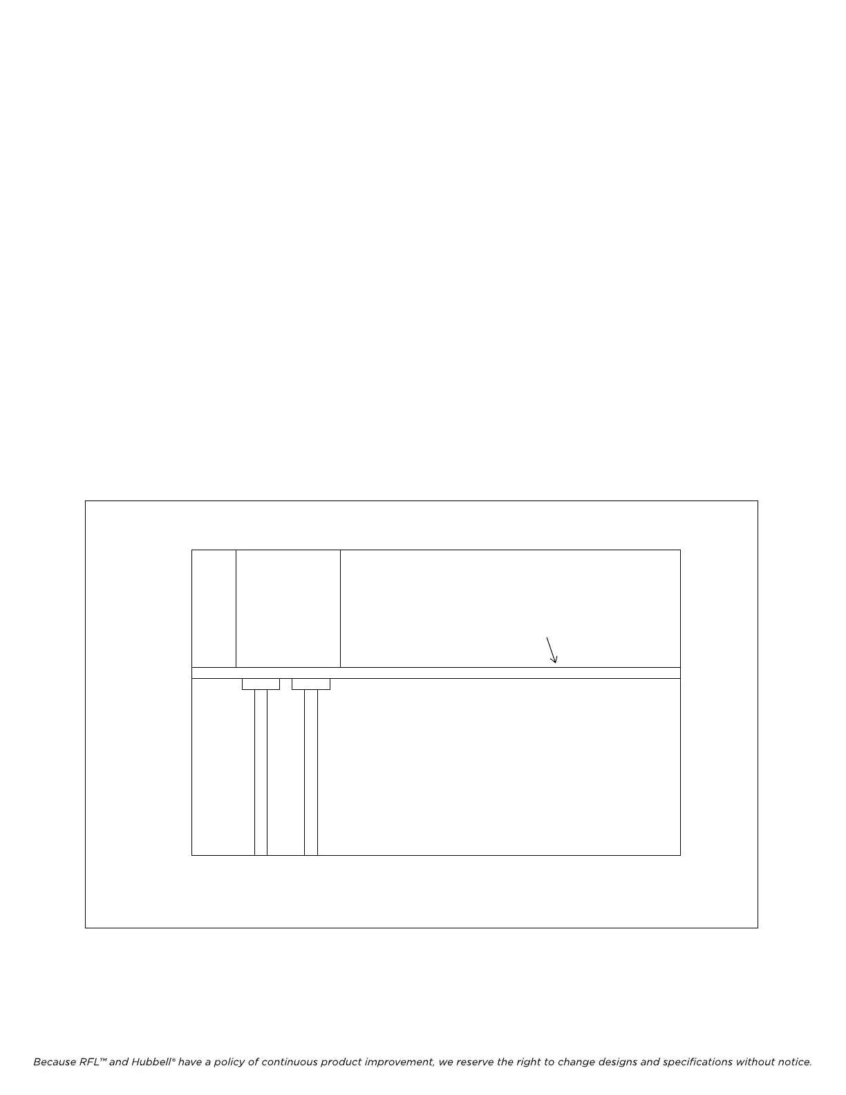
Redundant Common Module slots associated with the Redundant Module Adapter are dedicated. The
left-most slot is for the Standby CM4; and the next slot to the right is for the Main CM4. Some Module
Adapters are 3-slots wide. In this case, the third position is unused.
Main
Common
Module
Standby
Common
Module
Module Adapter
Backplane
Top View
Figure 3-1. Top view of IMUX 2000 chassis showing locations of Standby and Main Common Modules.
IMUX 2000E1 RFL Electronics Inc.
January 23, 2004 3-1 (973) 334-3100